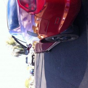
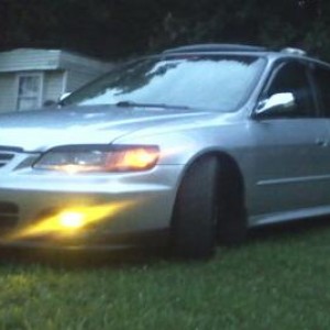
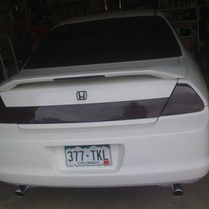
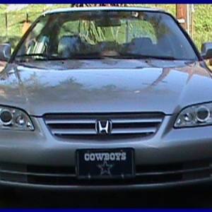
Hate to start another thread, but I would like to know which swap I should put my accord. I will be getting my first job, and so I would like to do a swap. My goal is ~250 whp. I need to pass emissions and inspections, and I would like to stay Obd2. I just do not know which engine is easier to maintain, has more aftermarket support, and will be cheaper to get hp out of. People may not agree with me, but I would like to stay automatic because this is my daily driver. I am planning on getting a manual 300zx for fun. I just want an enjoyable daily. Again, this is all an idea at this point. Unfortunately, my parents may not let me do a swap. But I would like to get it planned out just in case.
I hope this help in making a better buying choice because sometimes its not the amount of HP the engine makes but how much works it takes to run.
Accord_SiR Accord_SiR is offline
Junior Member
Points: 970, Level: 8 Points: 970, Level: 8 Points: 970, Level: 8
Activity: 0% Activity: 0% Activity: 0%
Join Date: Apr 2013
Location: Tucson, Az
Posts: 19
Rep Power: 0
Accord_SiR is somewhat reliable
Member Photo Albums
Jdm h23a vtec blue top swap guide
Hope this helps future people out with there swap mine was '00 Accord Ex F23A4 ULEV to H23A Vtec Blue top, only problem im having is temp gauge not working and A/T shifting hard in 1st gear, still no answers to why..
6th Generation Accord (EX ULEV VTEC) to JDM F20B DOHC (Automatic Transmission)
No one really has an in depth write up on this swap, as it is an extremely rare swap. That being said, who would want to slug down a 200hp DOHC Vtec with a restricting automatic transmission? Someone who wants a motor with noticeably more power (even if you aren’t getting the whole 200 to the wheels) than the F23A4, and someone who commutes for a good portion of the week. Rather than dropping in another F23 when the motor starts dying, have some fun (insert your definition of fun here..) and do a little swap for some gains. You could do an H22 swap instead, but bye-bye gas mileage. The F20B is basically a de-stroked H22, which means less fuel consumption at the same rpms. Less power as well, but we’re not building a racer here.
First thing you need to do is find the 200hp F20B. The m/t version is roughly 200hp, and the a/t version is around 180hp. You’ll be able to tell the difference by the throttle body on the intake manifold. The manual has a larger 62mm throttle body with a single throttle cable slot, and the automatic has a 58mm throttle body with a dual cable slot for the cruise control cable. You should be able to talk to the boys at
www.jspecauto.com and let them know what you’re doing. They’ll set you up with the motor and correct auto transmission you need. Or just get the motor and bolt your F23A4 transmission to it, the jdm transmission is way better however.
Do it right and get the PCB ECU along with the motor, but make sure it’s an auto version. Running your stock ULEV ECU will not run this motor correctly. I’m sure you could get a “chipped ECU” mapped for an H22 to work, but I’m not into tuning and just wanted good gas mileage and a solid motor.
Your stock wiring harness will do the trick, so don’t hack it up. All we’ll need to do is lengthen a few sensor plugs, change some over and re-pin some wires at the ECU harness. F20B is right hand drive, so the harness would be way too short in most spots and require twice the work to install properly. It IS a good idea to have Jspec send the harness with the motor as a reference point though. You’ll also need some of the plugs from that harness.
Alright, now we shop for parts. Things you’ll need:
-98-01 prelude power steering pump bracket
-98-01 prelude power steering pump and belt (Or keep your pump and buy the prelude belt, it’ll work)
-f23a4 a/c pump and bracket (Keep your old one, DON’T disconnect the lines)
-f23a4 crank pulley (Either buy one, or buy the tool to hold yours still while you crack the bolt loose with your foot and a 4’ breaker bar haha)
-Prelude/Accord harmonic balancer removal tool (to take the crank pulley off of the F20B and swap it)
-f23a4 main drive belt (keep your old one or buy one)
-98-01 prelude downpipe (you’ll need to cut it down to size and re-weld the flange)
-JDM Shift Solenoids and speed sensors (have Jspec send you undamaged sensors with intact plugs)
-F23a4 alternator (Pulley size is larger than F20b’s, makes the belt tension less of a headache)
-Non ULEV pre-cat O2 sensor, buy an” NTK 333-H9” sensor (Honda part # 36531-PCA-004). That’s the stock F20B sensor, the PCB ECU is PICKY! Use Only “Denso” or “NGK/NTK”. Don’t buy “Bosch” or any other replacement brands as they will fail in a few hundred miles, trust me. (They’re cheaply made and sold at AutoZone)
-2 ½” to 3” rubber intake sleeve coupler (to compensate the larger throttle body to your stock intake arm) you can find this at any auto parts store. Or have Jspec see if they can get ahold the F20B intake arm and box. It’ll look like this:
Note the Oval shape connection at the box. It’s the only box that’ll fit the F20B’s bigger throttle body on the throttle side. I feel using the F23A4’s intake setup with the reducer sleeve somewhat “chokes” the new motor; the throttle body is bigger for a reason so feed it what it needs! I don’t know that doing the reducer sleeve setup actually decreases performance however.
-5 quarts of Honda Automatic Transmission Fluid (Must get the Honda brand from the dealer, it’s formulated specifically for Honda transmissions, don’t kill your tranny with the AutoZone special)
- Plenty of Coolant, 5W30 Oil and Power Steering Fluid (Now that isn’t brand specific, any will do)
-Going to an auto parts store and buying a service manual is a great idea for torque specifications and how-to’s. It’ll clear up anything I don’t go into great detail on.
-Lots of latex gloves or a nice pair of mechanic’s gloves, unless you like black doors, light switches and whatnot in your house!
The Dirty Work
On a friendly safety note: there’s going to be an array of fluids coming out of engine tubes and getting all over the place in the removal process. Have plenty of rags ready, or put cardboard down everywhere. If you get anything in your eyes (Coolant etc..) get a shot glass with water in it, seal it over your eye and tilt your head up. Blink slowly about 5-10 times and you’re good. These fluids are horrible for your eyes and I dealt with it a lot while wrenching over the years. Water is your key to decontamination.
*Here We Go*
-Start by draining all the fluids; oil, coolant and transmission fluid. Next disconnect the battery and remove it, remove the air intake tube, box and battery tray.
- Remove the radiator hoses and the radiator. Make sure to disconnect the power harness to the radiator fans.
-Remove the throttle cable, cruise control cable and any vacuum lines coming from the canister system and tank to the manifold.
-Purge the fuel system by cracking the white plastic covered purge control valve on the fuel rail open with a wrench. Place a rag over it to avoid spray. Don’t light a cigarette. Now remove that fuel feed line and the return line from the purge control solenoid on the intake manifold. (little black cylinder in line with the solenoid)
-Start disconnecting all the engine harness sensor pugs you can find, there are a few behind the motor you can’t see. You may have to attack them from underneath the car.
-Remove the hood from your car and set it aside, it’s not as heavy as it seems.
-Remove the power steering pump, alternator and air conditioning compressor from the engine. Leave the A/C pump in the engine bay and leave the lines connected. Just sit the unit on the frame where the radiator used to be. DO NOT disconnect those lines!
-Disconnect the exhaust system from the downpipe to the catalytic converter. You can take the exhaust headers off to free up some engine bay space.
-If you have a 36mm socket and an impact gun or long breaker bar, you can remove the center spindle nut from the wheel hub, but it’s not necessary. Plus you have to un-dent the lock nut and re-dent it later. This allows you to get the half shafts better out of the way though. If you’re going to do this, crack it loose along with the lug nuts while the wheels are on the ground.
-Put the car on jack stands and remove the front wheels, lower ball joints, shock damper forks, and steering arm ball joints from the wheel assembly behind the rotors. There are cotter pins on both the lower ball joint nuts. Save these for reinstallation.
-Get a pry bar and put it in the space between where the half shaft meets the transmission. Pry it out carefully until it comes out easy. There’s a snap ring in there that needs to be disengaged. Do this for both sides obviously. Don’t damage the black rubber seals in the transmission side.
-Pull the half shaft out of the tranny while lifting up on the front wheel assembly with a jack or your friend with no job, and maneuver it out of the way so it doesn’t snap back into the transmission.
-Make sure all of your engine harness connectors and hoses from the fuel system etc. are disconnected, otherwise you’ll break them when you’re pulling the motor out. Now take off those harness stays all over the motor, and that harness connector grounded by the 10mm screw on the driver side of the intake manifold if you didn’t see it. Your motor should be held in by only the motor mounts at this point.
-Borrow your buddy’s engine hoist (cherry picker) and attach the two drop chains to the hoist points; one near the front of the valve cover, and one of the brackets on top of the transmission side. These hoist points are solid steel and located in three locations on the transmission and one on the driver side in front of the valve cover.
- You can remove the top of your intake manifold to ease the removal process if you’d like, but not necessary if you have a person to guide the motor out while you jack it up. Just don’t smash your upper firewall!
-Take the slack out of the chains by jacking the lift until there’s a little play in the chains. Careful not to lift too much, you’ll take the car off the jack stands! It’s never good when a car with no suspension or wheels hits the concrete…..
-Start removing the motor mounts; Front first, then the rear and finally the two sides.
-Coax that motor out of the engine bay and sit it on a pallet, spare tire or doubled up cardboard box on the old garage floor.
Congrats! You just did the easy part.
Wiring for the PCB ECU
So the PCB ECU has quite a few different pin-outs than the F23A4 ECU. We’ll start with the stuff that gave me headaches towards the end of the job. You’ll keep your F23A4 wiring harness through the whole deal, just swapping a few pins here and there.
O2 Sensor Wiring
-The PCB doesn’t utilize a secondary O2 sensor, so at the ECU harness you’ll want to de-pin A8 (blk/wht) and A23 (wht/red) and tape off the exposed pin connectors. This way there’s no random power going into the PCB ECU in places it doesn’t recognize, and you can salvage the sensor wires in case you want to go back to the ULEV motor. Now either leave the Secondary O2 sensor itself in the cat, or remove it and plug the hole with a threaded plug.
-As for the primary O2 sensor, some wiring will come into play. This link (
http://www.6thgenaccord.com/forums/s...ad.php?t=38508) will show you how to bypass the relay, however there is an error in this write-up. You do indeed move pin B19 to C1 at the ECU harness, however it’s the red wire at C14 that you will move to C16. After that you will de-pin C15 (blu) and tap it into the grn/blk wire at C18 (Sensor Ground 2). Keep C18 pinned; just use a wiretap to join the wires. When I say “tap into” in the future I mean in this matter.
If you do the conversion the way that link shows, you will get a check engine light for “Primary O2 sensor heater circuit” and the car will run extremely rich and spit black soot on the ground. It also doesn’t cover completing the circuit by tapping into C18 with C15. I had to spend hours staring at wiring diagrams and check engine lights to figure that out!
-You’re going to have to extend the O2 sensor wires to reach from the front engine connector to near the catalytic converter more or less. Your new downpipe with have the O2 sensor sitting somewhere under the oil filter behind the oil pan.
Fuel Pump Relay
-Now look at the grn/yel wire at pin A15 on your ECU harness. That’s the fuel pump relay, and we need to de-pin it and move it one over to A16. Now the car will start and run.
IAB Wiring
-You are now equipped with IAB’s, and in order to make these useful, look at the sensor connector on the little black box under the intake manifold. You should find a matching plug for the sensor on the F20B harness. It will have a yel/blk wire and a pnk/blu wire on it I believe. You’ll tap the yel/blk wire into the yel/blk wire (12v power source IGP1) on the ECU harness at pin B1. The other wire you will pin in at B16 on the ECU harness. The grn/red wire that was in B16 before can be de-pinned and taped off as it was a part of that messy primary O2 sensor relay you bypassed. So just de-pin a B harness wire from the hacked F20B harness and solder it to the pnk/blu IAB wire so you can simply insert it into the empty B16 spot on the harness in your car.
Speed Sensors
-You will need to modify your speed sensor harness plugs to fit the three wire JDM sensors. Cut your 2 wire harness plugs and splice on the 3 wire JDM plugs. The wires from the JDM side go color for color on your F23A4 harness. Now, you’ll have that 3rd wire on those sensors to worry about. They need to get tapped into a 5v reference wire to work properly. You can find this on the TPS or MAP sensor at the throttle body, or do it clean and tap into the ECU harness at C19 or C28 (VCC1 and VCC2). Tap both wires into one of those or one on each, either way its 5 volts to each sensor.
Distributor Wiring
-You’ll notice your F20B distributor has an 8 wire plug on its harness. Your F23A4 had a 4 wire plug. A bit confusing I know. Well look at the driver’s side of your F23A4 and notice the 4 wire harness plug coming out of the crank case. Cut that puppy off, but leave enough wire to splice it on again if you ever want to go back. Now look at the F23A4’s distributor. Cut that harness connector off as well, you’re going to have to take off the cap though.
Now that you have these two harness plugs, look at the colors on each wire. They go color for color to the F20B’s distributor plug. So extend the wires from the F23A4’s crank sensor harness to reach the F20B’s distributor. Do the same for the F23A4’s distributor plug if needed. Now you should be able to connect the two sides of the F23A4’s harness plugs (dizzy and crank), and have the 4 wires of each plug hanging out. Take the F20B harness side connector and wire in the two harnesses you just made to it, color for color. Now plug that harness connector into its mate at the distributor. That’s it; you’re playing with spark now.
-Take a look at the ECU pin-outs for the F23A4 and the F20B I’ve attached. You’ll notice most of the harness pins are the same. You’re not going to have traction control on your accord, so don’t worry about that. The ECU for the F20B will throw a “soft code” (Code 36) that doesn’t turn on your check engine light. It will throw the traction control code if hooked up to a scanner though. It won’t affect the vehicle’s operation at all however.
Miscellaneous Sensors
I know you can swap the oil pressure sensor on the back of the motor near the oil filter from the F23A4 to the F20B so you can utilize theF23A4 harness connector. You can also cut and splice the connector from harness to harness to utilize the F20B sensor. The only difference in connection is one is a slide in prong, and the other is a screw on. I cut my F23A4 harness plug off, and wired the F20B sensor connector on to use the F20B sensor already in the motor. That’s the screw on connector and I liked that idea better so I’m running JDM sensors.
Everything else is pretty much common sense, match wire colors and if the plug is different; splice it. I’m not sure you have to do any more splicing though.
Also, the F20B does not have a VTEC oil pressure sensor. That’s the one near the EGR valve and coolant temp sensor. You’ll notice you’re going to have a harness connector there that doesn’t plug into anything. That’s fine let it hang; the PCB ECU doesn’t recognize that sensor and doesn’t need it to activate VTEC.
Vacuum / Hardware modifications
-You’re not going to have cruise control anymore, so kiss it goodbye. You’re not going to have enough vacuum ports on the intake manifold to hook up the actuator. Even if you did, the ECU doesn’t recognize it. So just leave the little round tank unhooked, it’ll be fine. You can either remove the cruise actuator (that’s on the driver side of the engine bay) or leave it there, coil up the cruise throttle cable and zip-tie it neatly out of the way.
-The only difference in vacuum routing is the Purge control solenoid valve hose routing. Instead of having it hook into the front of the manifold near the valve cover, it goes on the front of the throttle body; there will be a vacuum stem there for it. The solenoid itself will no longer mount on the intake manifold as there are no mount holes for it on the F20B intake manifold. I just extended the harness plug approximately 8” and mounted the solenoid on the firewall above the intake manifold with two self-tapping screws. You can put it wherever you want really, just make sure it’s stable and doesn’t move wherever you do put it.
- Everything else vacuum related; just find a vacuum stem on the manifold and plug it up!
Throttle cable
-You’ll have to fashion your own throttle cable bracket; as the F23A4 cable is a bit longer than the F20B’s and there will be way too much cable play to be able to adjust. You can buy some metal plate from the hardware store and make a new bracket base to go on the intake manifold. Then drill holes for the manifold mount bolts, and holes for the cable bracket. You’re basically using the plate to extend the reach of the bracket.
You’ll see what I mean when you try to attach the cable to the manifold prior to modifying it.
If you want to get fancy you can bend and weld one up from scratch and powder coat it, this would be pretty nice and give a stock appearance.
Installing the motor, ECU
-Drop the motor in the bay in the reverse order as removal. Pretty straightforward, go by the manual’s torque settings and you’ll be fine.
-You’ll notice you’re going to have to bend the metal tube portion of the power steering hose to get it to be seated flush on the pump. Heat it with a torch and bend it downward until the connection is flush. You also have to bend the oil dipstick to the right toward the wheel well to allow the hose to sit next to the valve cover. Just literally move it with your hand and it’ll bend. No harm in doing so, just don’t bend it more than needed to clear the power steering hose.
-Swap the ECU’s out, putting the PCB ECU in place of the old one. It will bolt right into place with no modification whatsoever.
-After everything is in place; double check your harness connections, vacuum connections and all hoses and fuel lines. Make sure everything is correct and make sure you have all the engine mount bolts torqued to specification.
-If you bought an aftermarket prelude header and downpipe for the exhaust, get the downpipe shortened to the proper length at the cat connection. Lay it up under the motor and make good measurements. Go get it cut and welded and install it.
-Fill the motor with the correct amount of fluids and double check all your work again.
Conclusion
It’s not the easiest of swaps, but it does bolt up nicely with no modification to motor mounts. I have not found a write up on this swap so I decided to document it. There is a lot of useful information on the internet for issues you may run into that I didn’t cover. I covered the specific issues which I could not find online, and you shouldn’t have too much trouble after following this guide.
Now go drive your new car.


