

Hey guys, I haven't been on here for quite awhile, been posting here and there lately but not too much. I figured I would come back with this DIY.
So I recently blew my head gasket and got it replaced. Problem is, my temp gauge now fluctuates between 1/3 and 7/8 hot. The shop tested it, and said that it runs at normal operating temp. Which is fine, so I needed an aftermarket water temp gauge. I chose the Autometer Z series short sweep electrical gauge.
This is for the 4 cylinder, but the V6 should be relatively the same, just the sender will be in a different spot. See Haynes manual.
Note: This will disable the stock temp gauge.
Time: A few hours
Difficulty Level: 2 out of 10
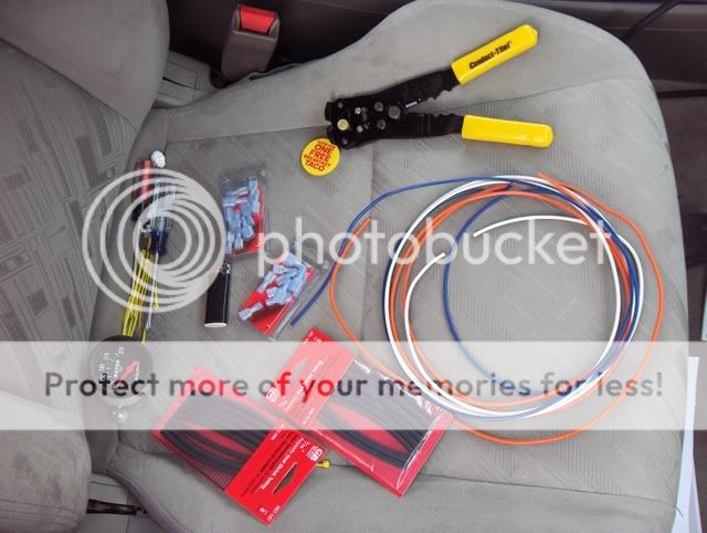
What you need:
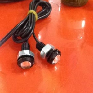
The tools/materials I used were: 16awg wire, preferably at least 3 different colors, wire stripper, heat shrink (electrical tape can be used), a lighter, a philips head screw driver, blue female connectors (blue because that is 14-16awg), a couple ring terminals, and of course the gauge and sender unit (not pictured).
Step 1:
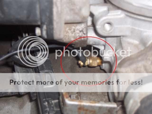
The autometer gauge came with a sender unit. You will need to remove your stock sender unit and put in the Autometer one. Make sure your engine is cool first, or else you will get burned. Once the stock one is out, put the Autometer one in quickly, because coolant will leak out.
Here is a pic of the sender with wire attached. The sender is circled
I chose to use black wire in the engine bay because it is less noticeable. Inside the car I will splice it with another color so it is not mistaken for a ground.
Attach the ring terminal to the wire, and place it on the sender. Attach nut.
Step 2:
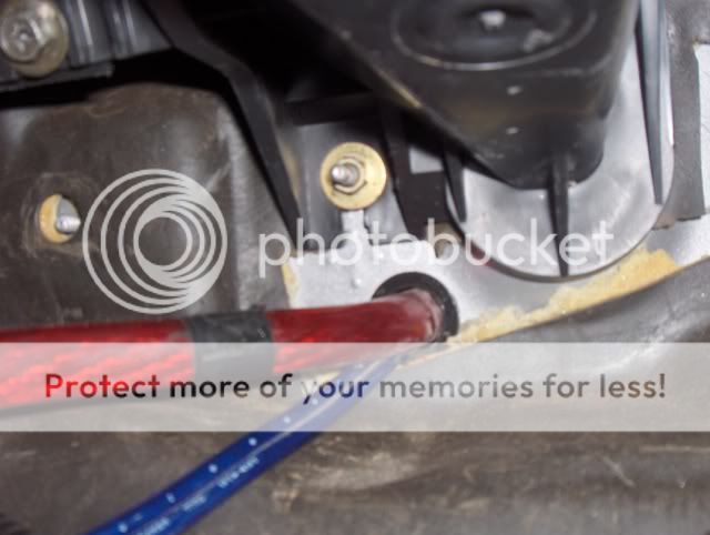
Now you're going to have to run the wire into the cabin. I chose to run it through my firewall where my power wire for my amps and a few other wires are ran. This is not a factory hole that I just popped out a grommet, this is a hole that I drilled.
Step 4 (Optional):
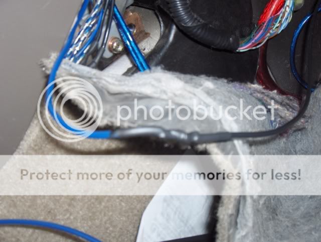
Like I said before, I wanted to splice a different colored wire with the black one, so I chose blue because water is blue. Sorry for the blurry pic.
Step 5:
The gauge needs power, so I needed to hook it up to an ignition source. My SRS light was on for awhile, and I unplugged the indicator light in the cluster anyways, so I stuck the wire in the SRS fuse slot. If you have a spade connector, that will work best. Just cut off one the the slots. Unfortunately, I did not have one, so I had to improvise. I cut up a male slot connector in half so it looks like this.

Now just stick it into the fuse slot.
Now, there are other ways, and better ways to hook your gauge to an ignition source. You can follow Andy's writeup here to install a volt meter to see where to splice your wire. However, I don't like splicing into factory wires, so I did it a different way.
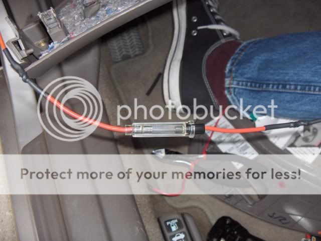
The gauge needs to be fused, so I ran an inline use.
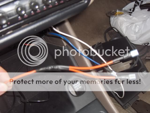
I ran the wire under the steering wheel to under the radio, where the stock tape player is (or the "third din"). I also ran the sending wire (the blue/black one) here as well. I wanted to put the gauge in the bezel gauge pod, but I got one from eBay and it fit like poo. So I am putting it here for now.
Now, I also installed a volt meter at the same time, so I split the wire into two and put on slot female connectors.
Step 6:
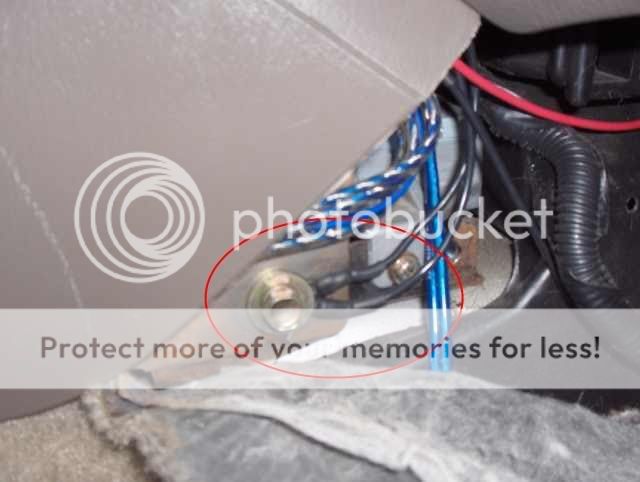
The gauge(s) also need to be grounded. So I took a ring connector and grounded it. There are 2 grounds here, one is for the actual gauge, the other is for the lights to the gauges. This can probably be one wire and spliced. But since I was installing 2 gauges (therefore 2 lights) I would have to splice it 4 ways. Next I ran these wires to under the radio, the same place as the power and sending wires.
Step 7:
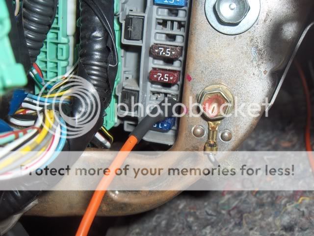
The light for the gauge needs power as well. You can choose to have the light turn on with ignition, and run the wire to the same place as the wire that powers the gauges, or wire it so they only turn on with the headlights. Once again, you can use Andy's write up to see which wire to splice it into, but, once again, I decided not to splice into any factory wires. So I decided to run it into the fuse box again. However, I couldn't find any inside the cabin that got power once the lights were on, so I had to run the wire into the engine bay to that fuse box. I wired it to the passenger head light fuse. So I ran the wire through the same hole as the sending wire.
Once the wire is ran to the fuse box, I drilled a small hole in the fuse box to run the wire. Once again, I cut up a male spade connector. (Sorry for the bad pic)
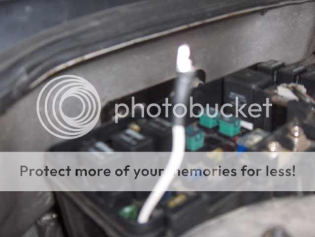
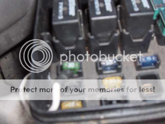
Then put the connector into the fuse slot. You have to put it in the right slot, otherwise the gauge light will be really dim. Once that wire is in, and I made sure the light turned on, I shoved the head light fuse in. (Sorry again for the blurry pic, it will be replaced soon)
This wire should also be fused, but I only bought one inline fuse. Since I am installing two gauges, I spliced the wire again to the two light wires. I didn't grab a pic though, but it looks the same as the spliced power wire.
Step 8:
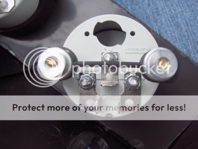
Now it is time to hook up the gauges. The top connector is for the ground, the right connector is for the ignition, and the left connector is for the sending wire. For the volt meter, the sending connector is not used.
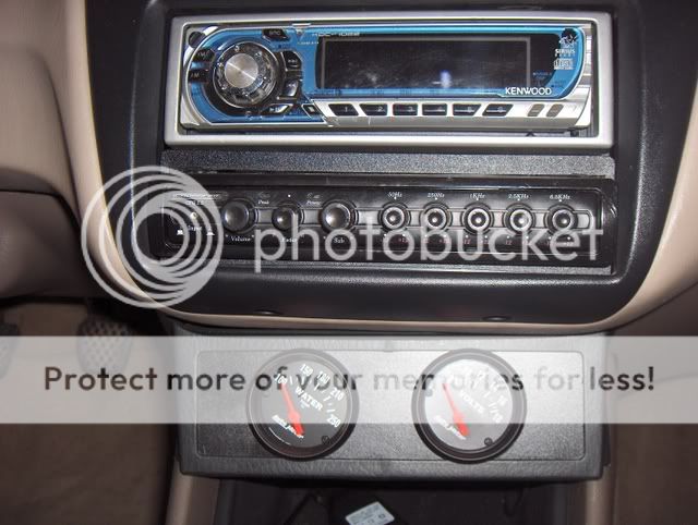
A buddy of mine with a 6th gen (DEP I might add) had the factory tape deck. He had no need for it so we yanked it out and he gave me the bezel. So I cut up a piece of plastic tray, got a 2" hole saw and drilled two holes, painted it, and glued it in.
Here is what it looks like.

And with the gauges.
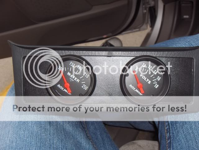
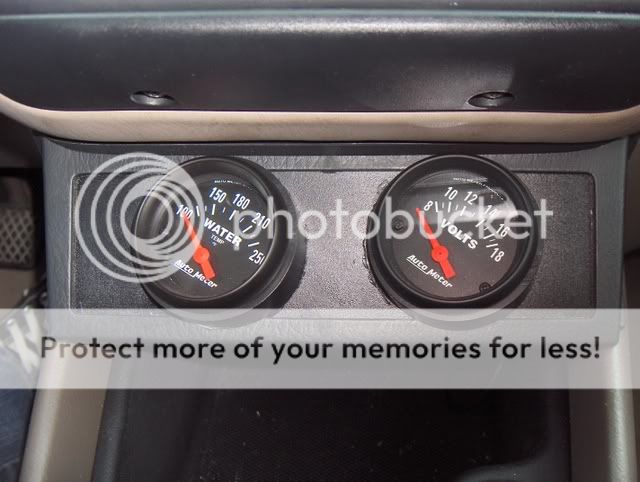
Now hook the wires to the connectors on the gauges, stick the gauges where you want them, and you're good to go.
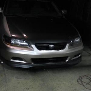
Pics of the gauges installed
Here is what they were originally, but due to the angle I couldn't see them very well.
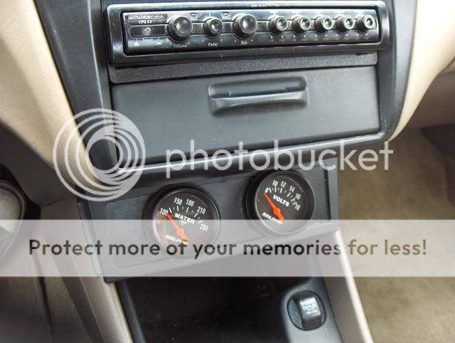
So I got some PVC pipe, cut it at a 15 degree angle, and now I can see them!
The PVC slipped while it was drying that night, so it looks kind of like poo around the edges.
More pics


I hope this helps anyone who wants to install an electric water temp gauge. I'll try to answer any questions anyone might have.
So I recently blew my head gasket and got it replaced. Problem is, my temp gauge now fluctuates between 1/3 and 7/8 hot. The shop tested it, and said that it runs at normal operating temp. Which is fine, so I needed an aftermarket water temp gauge. I chose the Autometer Z series short sweep electrical gauge.
This is for the 4 cylinder, but the V6 should be relatively the same, just the sender will be in a different spot. See Haynes manual.
Note: This will disable the stock temp gauge.
Time: A few hours
Difficulty Level: 2 out of 10
What you need:
The tools/materials I used were: 16awg wire, preferably at least 3 different colors, wire stripper, heat shrink (electrical tape can be used), a lighter, a philips head screw driver, blue female connectors (blue because that is 14-16awg), a couple ring terminals, and of course the gauge and sender unit (not pictured).
Step 1:
The autometer gauge came with a sender unit. You will need to remove your stock sender unit and put in the Autometer one. Make sure your engine is cool first, or else you will get burned. Once the stock one is out, put the Autometer one in quickly, because coolant will leak out.
Here is a pic of the sender with wire attached. The sender is circled
I chose to use black wire in the engine bay because it is less noticeable. Inside the car I will splice it with another color so it is not mistaken for a ground.
Attach the ring terminal to the wire, and place it on the sender. Attach nut.
Step 2:
Now you're going to have to run the wire into the cabin. I chose to run it through my firewall where my power wire for my amps and a few other wires are ran. This is not a factory hole that I just popped out a grommet, this is a hole that I drilled.
Step 4 (Optional):
Like I said before, I wanted to splice a different colored wire with the black one, so I chose blue because water is blue. Sorry for the blurry pic.
Step 5:
The gauge needs power, so I needed to hook it up to an ignition source. My SRS light was on for awhile, and I unplugged the indicator light in the cluster anyways, so I stuck the wire in the SRS fuse slot. If you have a spade connector, that will work best. Just cut off one the the slots. Unfortunately, I did not have one, so I had to improvise. I cut up a male slot connector in half so it looks like this.
Now just stick it into the fuse slot.
Now, there are other ways, and better ways to hook your gauge to an ignition source. You can follow Andy's writeup here to install a volt meter to see where to splice your wire. However, I don't like splicing into factory wires, so I did it a different way.
The gauge needs to be fused, so I ran an inline use.
I ran the wire under the steering wheel to under the radio, where the stock tape player is (or the "third din"). I also ran the sending wire (the blue/black one) here as well. I wanted to put the gauge in the bezel gauge pod, but I got one from eBay and it fit like poo. So I am putting it here for now.
Now, I also installed a volt meter at the same time, so I split the wire into two and put on slot female connectors.
Step 6:
The gauge(s) also need to be grounded. So I took a ring connector and grounded it. There are 2 grounds here, one is for the actual gauge, the other is for the lights to the gauges. This can probably be one wire and spliced. But since I was installing 2 gauges (therefore 2 lights) I would have to splice it 4 ways. Next I ran these wires to under the radio, the same place as the power and sending wires.
Step 7:
The light for the gauge needs power as well. You can choose to have the light turn on with ignition, and run the wire to the same place as the wire that powers the gauges, or wire it so they only turn on with the headlights. Once again, you can use Andy's write up to see which wire to splice it into, but, once again, I decided not to splice into any factory wires. So I decided to run it into the fuse box again. However, I couldn't find any inside the cabin that got power once the lights were on, so I had to run the wire into the engine bay to that fuse box. I wired it to the passenger head light fuse. So I ran the wire through the same hole as the sending wire.
Once the wire is ran to the fuse box, I drilled a small hole in the fuse box to run the wire. Once again, I cut up a male spade connector. (Sorry for the bad pic)
Then put the connector into the fuse slot. You have to put it in the right slot, otherwise the gauge light will be really dim. Once that wire is in, and I made sure the light turned on, I shoved the head light fuse in. (Sorry again for the blurry pic, it will be replaced soon)
This wire should also be fused, but I only bought one inline fuse. Since I am installing two gauges, I spliced the wire again to the two light wires. I didn't grab a pic though, but it looks the same as the spliced power wire.
Step 8:
Now it is time to hook up the gauges. The top connector is for the ground, the right connector is for the ignition, and the left connector is for the sending wire. For the volt meter, the sending connector is not used.
A buddy of mine with a 6th gen (DEP I might add) had the factory tape deck. He had no need for it so we yanked it out and he gave me the bezel. So I cut up a piece of plastic tray, got a 2" hole saw and drilled two holes, painted it, and glued it in.
Here is what it looks like.
And with the gauges.
Now hook the wires to the connectors on the gauges, stick the gauges where you want them, and you're good to go.
Pics of the gauges installed
Here is what they were originally, but due to the angle I couldn't see them very well.
So I got some PVC pipe, cut it at a 15 degree angle, and now I can see them!
The PVC slipped while it was drying that night, so it looks kind of like poo around the edges.
More pics
I hope this helps anyone who wants to install an electric water temp gauge. I'll try to answer any questions anyone might have.
Last edited:
")