

For those of us unlucky enough to have a ULEV automatic, and you did a manual swap, but had to use a regular VTEC ECU because 5speed ULEV ecus are rare, This Write Up is for you.
*Tools Required*
10mm Socket /w Ratchet (bracket)
Philips Head Screwdriver (remove Panels)
Small Flat Head (push up ECU connector Lock)
Pair of Pliers (Pull Pin from ECU Connector)
Hook or Curved Pick (to remove clips)
Wire Stripper
PDF's Courtesy of Chid0, and Relay Pictures Courtesty of 001Stunna
I happen to be one of those unlucky ones who could not source a manual ULEV ecu to use with my swap, so I used a regular VTEC one instead. The problem with that though is that it will throw a CEL for O2 Sensor Heater Circuit (P0135). The thing is that the ULEV ecu uses different Pins for the Oxygen Sensor Heater Circuit on the ECU itself, so naturally Depinning will have to done.
PDFs:
http://freepdfhosting.com/603bc5b874.pdf
http://freepdfhosting.com/5bd477c96a.pdf
http://freepdfhosting.com/ed0483988f.pdf
ECU Pin Reference:
Before attempting any of this *MAKE SURE* you bought the correct O2 Sensor (I used NTK24655). The ULEV Ecu uses a 32-bit Wideband Sensor and the Regular VTEC uses a Narrowband.
1) First you want to Locate B19, Go ahead and Depin it. Should be Black/White wire. You are going to have to repin it to C1. Now Connector B's Pins are slightly larger and shaped a little differently than the pins in Connector C. So What I did was steal a Pin from Connector D and cut both wires and Join the Blk/Wht wire to the smaller pin.
2) Once you've repinned B19, the next step is to Repin C15 to C16 which is very simple since it they are on the same connector and the pins are the same. Go ahead and reinstall your ECU if you wish at this Point.
3) Now for the Fun part. Locating the O2Sensor Heater Circuit Relay and Jumping it. Now I already had my Glovebox, Passenger Underdash Cover, and Kick Panels Removed. You don't technically have to remove all that, but Id suggest it because the Relay is in a very tight spot. You do have to remove the kickpanel though.
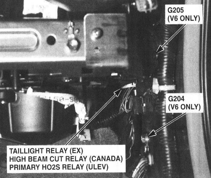
4) Now look for a 10mm bolt that is under the kick panel. It should be bolting down a metal clip, and on the end on that clip are 2 relays tucked off into the corner. Go ahead and remove the bolt to make it easier for yourself. *Please Note the Orientation of the Relay* You Do Not Want to Jump The Wrong Relay.
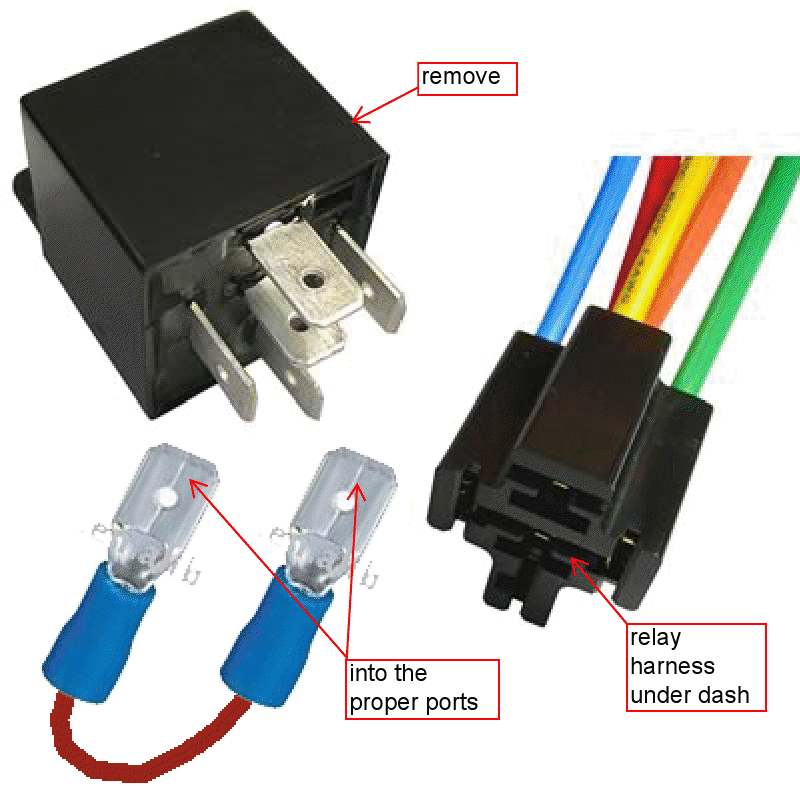
5) There is a Big White Plastic Clip that holds the Relays in. Use a curved pick or something similar to pull the clips up and remove it. Then remove the Relay. Look on the back of the Wiring Harness where you pulled the Relay and Note the Locations of the BlK/Yellow wire and the White wire.
6) *EDIT*Jumping the Relay: I talked to CHid0, and said he the better way to do this is to eliminate the relay all together. You are going to need 4 male connectors that can plug into the harness directly. So go ahead and get pieces of wire maybe about 4 inches long, then crimp the male connectors on each end. Then plug one end the male connector into where BlK/Yellow and the other end into White.
7) Now bolt the metal bracket for the relay back in, and put all clips, panels, back together again.
Now for the moment of truth, go ahead and plug in a code reader and delete whatever codes you have. If you did it right, there should be no codes after you turn the engine on.
There you have it, Thanks again to everyone that Helped including RussianRed, CHid0 and 001Stunna since i stole your 2 pics (dont kill me LOL). If you have any questions feel free to PM me and rep =P
*Tools Required*
10mm Socket /w Ratchet (bracket)
Philips Head Screwdriver (remove Panels)
Small Flat Head (push up ECU connector Lock)
Pair of Pliers (Pull Pin from ECU Connector)
Hook or Curved Pick (to remove clips)
Wire Stripper
PDF's Courtesy of Chid0, and Relay Pictures Courtesty of 001Stunna
I happen to be one of those unlucky ones who could not source a manual ULEV ecu to use with my swap, so I used a regular VTEC one instead. The problem with that though is that it will throw a CEL for O2 Sensor Heater Circuit (P0135). The thing is that the ULEV ecu uses different Pins for the Oxygen Sensor Heater Circuit on the ECU itself, so naturally Depinning will have to done.
PDFs:
http://freepdfhosting.com/603bc5b874.pdf
http://freepdfhosting.com/5bd477c96a.pdf
http://freepdfhosting.com/ed0483988f.pdf
ECU Pin Reference:
Before attempting any of this *MAKE SURE* you bought the correct O2 Sensor (I used NTK24655). The ULEV Ecu uses a 32-bit Wideband Sensor and the Regular VTEC uses a Narrowband.
1) First you want to Locate B19, Go ahead and Depin it. Should be Black/White wire. You are going to have to repin it to C1. Now Connector B's Pins are slightly larger and shaped a little differently than the pins in Connector C. So What I did was steal a Pin from Connector D and cut both wires and Join the Blk/Wht wire to the smaller pin.
2) Once you've repinned B19, the next step is to Repin C15 to C16 which is very simple since it they are on the same connector and the pins are the same. Go ahead and reinstall your ECU if you wish at this Point.
3) Now for the Fun part. Locating the O2Sensor Heater Circuit Relay and Jumping it. Now I already had my Glovebox, Passenger Underdash Cover, and Kick Panels Removed. You don't technically have to remove all that, but Id suggest it because the Relay is in a very tight spot. You do have to remove the kickpanel though.
4) Now look for a 10mm bolt that is under the kick panel. It should be bolting down a metal clip, and on the end on that clip are 2 relays tucked off into the corner. Go ahead and remove the bolt to make it easier for yourself. *Please Note the Orientation of the Relay* You Do Not Want to Jump The Wrong Relay.
5) There is a Big White Plastic Clip that holds the Relays in. Use a curved pick or something similar to pull the clips up and remove it. Then remove the Relay. Look on the back of the Wiring Harness where you pulled the Relay and Note the Locations of the BlK/Yellow wire and the White wire.
6) *EDIT*Jumping the Relay: I talked to CHid0, and said he the better way to do this is to eliminate the relay all together. You are going to need 4 male connectors that can plug into the harness directly. So go ahead and get pieces of wire maybe about 4 inches long, then crimp the male connectors on each end. Then plug one end the male connector into where BlK/Yellow and the other end into White.
7) Now bolt the metal bracket for the relay back in, and put all clips, panels, back together again.
Now for the moment of truth, go ahead and plug in a code reader and delete whatever codes you have. If you did it right, there should be no codes after you turn the engine on.
There you have it, Thanks again to everyone that Helped including RussianRed, CHid0 and 001Stunna since i stole your 2 pics (dont kill me LOL). If you have any questions feel free to PM me and rep =P
Last edited: