H22 Swap

Drift

Well-Known Member
Joined
Aug 8, 2007
Posts
1,333
Reaction score
22
Location
Mass
This is pretty much every post that I made that was the least bit useful and/or helpful to anyone who is considering swapping an H22 into their 6th gen accord.
This thread has been severely pruned because doing this much took long enough. I can answer pretty much any question regarding this job, (and many others).


This information is all from my original thread on Everything-honda.com, which has unfortunately gone under. Another unfortunate event was the passing of imagestation.com;
which is where I had originally hosted all my pics. Some of which were uploaded directly from my camera, and never to my hard drive. So they are lost forever, :( .

I did my best to rehost and replace all the pics I could. I skipped some due to relevancy, others due to their absence.

I hope people find this information useful, its taken me all night to do. :D

01-24-2006, 10:00 PM
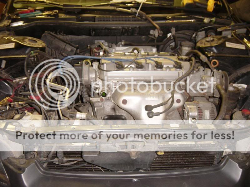
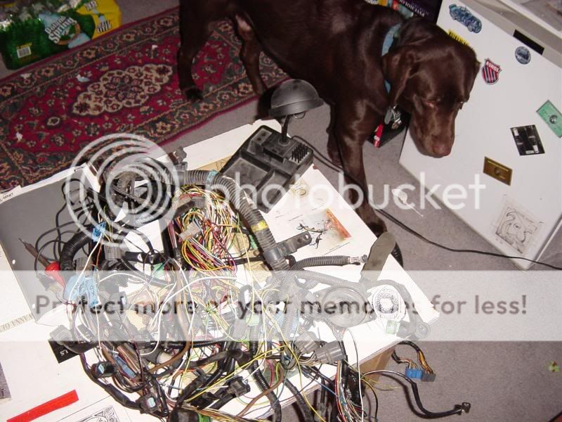
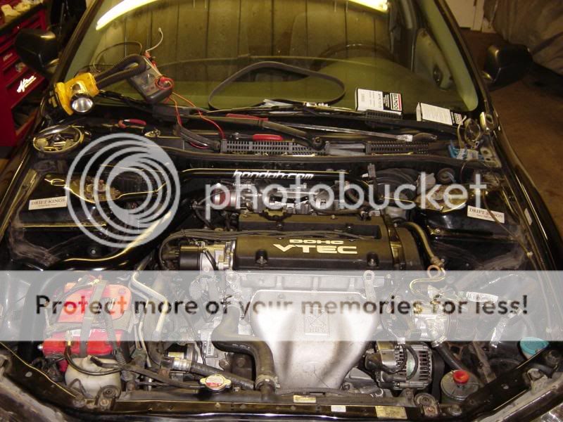
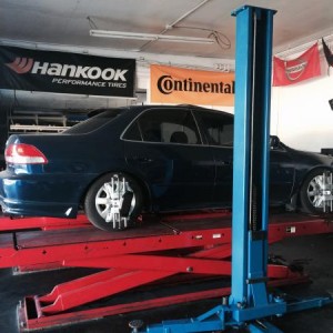
So the motor arrived today and it looks great. Steve at www.hmotorsonline.com hooked it up.

DSC03115.jpg


I was first told it was going to be out of a '93, but its actually out of a '95, Im not complaining.

DSC03116.jpg


JDM tIgHT yO!!1!1!

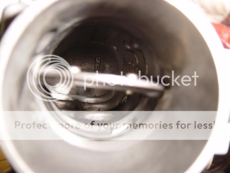
So today I took the tranny off and made sure it had the LSD, its did . I also took the pressure plate and clutch disc off to see what condition they were in. Used, obviously, but no bad at all. I took the die grinder with a sanding brush on it to the pressure plate and flywheel.


And the clutch disk still looks good. If my ACT is the same size, its going in the H22 though, no question.


After greasing up the input shaft, throwout bearing, and clutch fork again, I put the tranny back on.

As I was doing so, I say this:

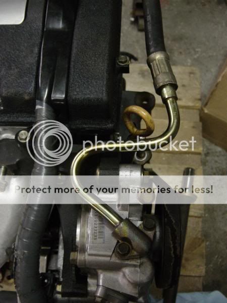
The two lines coming out of the tranny, as I later found out, are for the Rear Wheel Steering. I may use it for a tranny cooler later down the line.

DSC03128.jpg


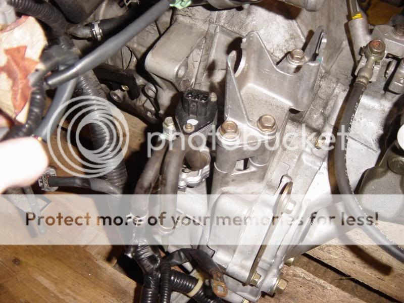
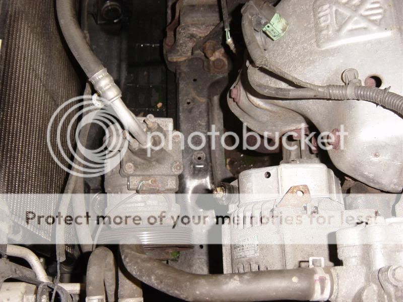
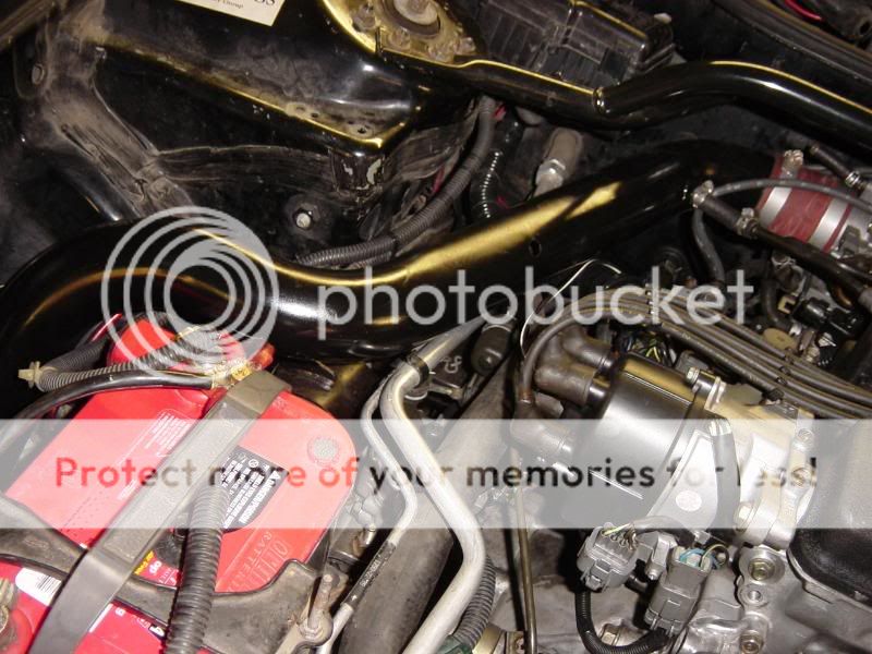
This is the motor mount that is different from the F23 mount. I am going to make a custom one to replace it.

Skunk2 Hooks it up again.

DSC03130.jpg


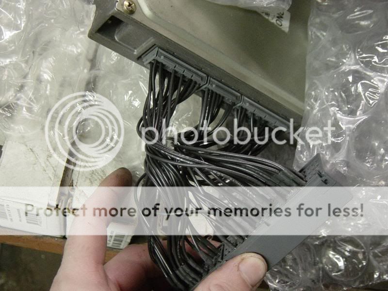
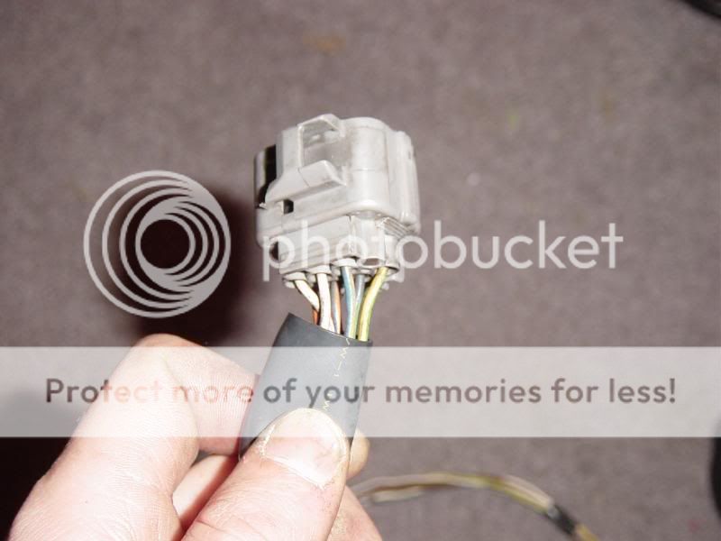
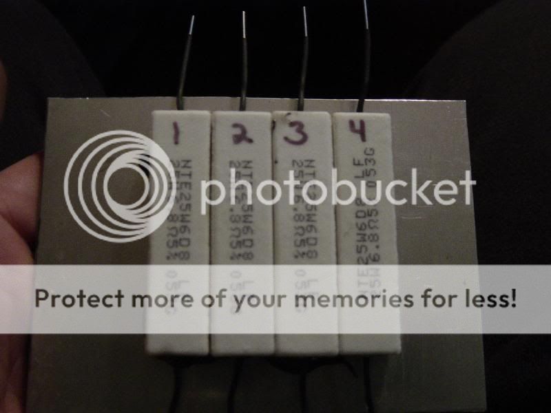
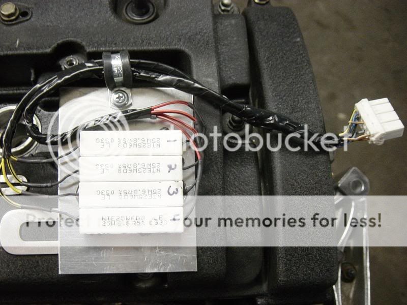
I still have to wire in VTEC into my harness.


The power steering line is different too. I forgot to take a pic today, Ill take one tomorrow.

I will be posting up pics continuously as I do the swap, so hang tight.


01-25-2006, 10:25 AM

2kAccord said:
Whoa, i dont know how i missed this thread. I didnt realize you were swapping so soon. The H-motor looks sick!

Whats the deal with the motor mount though, I though the f and h blocks were the same??
Ill take a pic of the f mount tomorrow to show the difference.


da_accordian said:
about the custom motor mount, I heard you can use the driver side motor mount from an Accord Euro R

Honda North America wont even let their dealrships get Canadian parts, let alone Japanese or UK parts. I am going to have to settle for a DSG custom, which is fine with me.
 

Drift

Well-Known Member
Joined
Aug 8, 2007
Posts
1,333
Reaction score
22
Location
Mass
1.52.06 3:08pm

I took some more pics when I went to the shop today. And by happenstance I saw NotoriousB's car there too, I took some pics and will post them in his thread.

This I found interesting. Can anyone tell me why?

DSC03132.jpg


Here is the p/s pump and you can see why its doesnt match up. The line to the pump is at a different angle. Talk of welding the stock one in place has passed through the shop, I have no objections.

DSC03133.jpg


The cams looked good. Pretty much brand new in fact.

picture 404

And as promised, I snapped a pic of the f23 driver's side engine mount to compare it to the h22.

(Courtesy of NotoriousB His hood was open right next to my motor )

DSC03161.jpg


The difference is obvious.


1.27.06 10:04pm

I was doing a bunch more research today at work, (we were really slow). I found out a few things that will be very helpful to know.


The H22 dizzy not only have the cylinder position sensors inside them, they also have a TDC sensor and a crankshaft position sensor.


So I will be needing to wire in those extra 2 sensors into the f series harness.


Also, the injectors require a resistor pack to limit the voltage they receive. This is to promote longevity of the injector field coils.
So I can either try to track one down in a junk yard or something, or wire in resistors into the injector harness's. I probably end up doing the latter of
the 2.


The diagrams for wiring up the distributor:

mr6977.jpg


mr6b2h.jpg


And the ECU pinout number locations:


mr6c1g.jpg
 
Last edited:

Drift

Well-Known Member
Joined
Aug 8, 2007
Posts
1,333
Reaction score
22
Location
Mass
1.29.06 7:07pm
So I got to work on the motor a little today.
It was nicely tucked into the motor corner at DSG awaiting my arrival.

DSC03194.jpg


DSC03196.jpg


DSC03197.jpg


DSC03198.jpg


Its rubbing elbows with race motors at the moment, maybe some HP will rub off on it

That is a fully built SR20det with Specs that can be found HERE/

The tools required to remove the crank pulley. (minus the DeWalt tool, that comes in later)


That tool holds the crank pulley in place while you spin off the bolt that is on with 181ft-lbs. I borrowed it from one of the techs at work.

On to my new favorite tool ever. My DeWalt 3/8" Impact gun. Anything you'd use a ratchet for, you can use this for. And it has 100ft-lbs max torque! It cuts down the time spent wrenching 10 fold.


I cleaned out the throttle body and took a quick look inside the intake manifold: Spotless, just like the rest of the motor.

DSC03182.jpg


And I also went ahead and replaced the timing belt, the balance belt and the waterpump.

DSC03180.jpg


The old waterpump looks brand spanking new!

Here are a couple pics of how the driver's side mount bolts up to the block. My hopes are that NotoriousB can post up some of his pics of his motor build with the timing belt side of the motor showing so I can see what the mount looks like on the f series.


(Thanks Brian)

As I was removing the wiring harness to figure out all the wires I need to add and so forth, I accidentally broke the knock sensor trying to get the connector off the ****ing thing. So I quickly called work and ordered a new one, $105 later it should be in the mail.

DSC03189.jpg


But on the bright side I got the harness off.

DSC03183.jpg


I brought the p13 home with me tonight so I can look at the pinouts and my day tomorrow.
 

Drift

Well-Known Member
Joined
Aug 8, 2007
Posts
1,333
Reaction score
22
Location
Mass
1.29.06 7:46pm
So, by the looks of it, the mounts will not swap over as I had hoped. No big deal. You will soon see some sick DSG custom motor mount action.

F23...........................................................................H22
F23vsH22enginemount.jpg


1.30.06 10:26am
jweller said:
congrats on joining the broken knock sensor club. I know Paul and I are both members, and i think there is sombody else here that is a member as well.

just a thought, could you save the $100 and swap the one off of your f23 onto the h22
I would have but my a5 motor doesnt have a knock sensor.


Jeff, Im not going nuts taking that **** apart. The motor is spotless, inside and out. Id be surprised if this actaully did have 38k miles on it and not 5k. Im replacing the stock clutch it came with the my ACT, and having done the t belt and ****, I think its all set.


1.31.06 7:44pm

Ok, so I went a whole day with no updates, but I was really tied up with all the wiring, (you'll get the pun once you see the pics).

I backed the car into the shop around 11:30am.


Then we went nuts tearing **** out.

DSC03200.jpg


About an hour or so later, were ready to puller out from the top pretty easily.

DSC03201.jpg


The easiest way we found was to remove the radiator, and place the a/c compressor in its place, still hooked up. Then remove all the motor mounts from the engine bay. This allows the tranny and crank pulley plenty of room. The intake manifold wasnt really an issue.


DSC03196.jpg


The easy part is over. On to the wiring. This has been a long and very tedious process. My intensions are to make the harness look stock, but I have to shange a bunch of ****. Such as:
Re-route the CKP and TDC sensor wires up to the distributor connector. I found the easiest way for me do do this was to start where they were in the stock f23 harness and wrap them around the back of the motor and up to where the distributor connects.

DSC03211.jpg


(Max Helped.)

The above pic was what I did last night. The harness is sitting as it would, (generally) on the engine. You are loking at it from the front of the engine, as if you just opened the hood. The white and brown wires that hook around to the back are the TDC, CKP, CYP and all the other distributor wires. I also had to swap over the alternator connector.

DSC03212.jpg


All that was last night.

DSC03214.jpg

*I have since changed the wiring to shorten the trigger wires to OEM lengths instead of having them wrap around the engine

Today I went to the electronic store and found my resistors. I needed any where between 6-8 ohms. I found some that ohm out to 6.9-7.0 ohms, perfect.

Above are labeled per cylinder.

DSC03219.jpg


Whoops! Where did this ACT StreetLite flywheel come from?!

And this is what I will partake in as I work this evening. The taskes I hope to accomplish are finish wiring in the injector resistor pack, wiring VTEC into my stock harness, and a knock sensor too, (which requires sheilded wire).

DSC03231.jpg

DSC03230.jpg


I also swapped over the h22 injector clips over to the f23 harness to use with the resistor pack. The stock f23 clips did not fit.
 

Drift

Well-Known Member
Joined
Aug 8, 2007
Posts
1,333
Reaction score
22
Location
Mass
2.01.06 1:01am

I finished as much as I could do on the harness. All there is left to do is soldier the injectors up to the resistor pack. I want to do that with the harness on the engine to make sure the lengths are appropriate.


I set it up the same way I had it before, as if you are looking at the motor.


The injector clips all wired up.


I had to wire in all the VTEC wires and the knock sensor, the F23a5 didnt have one.


VTEC wired into the ECU.


And I have to thank the good folks at Gerber for their quality tools. Without it It would have taken 5 times as long.

**Pics missing!! I had uploaded them directly to imagestation.com, which has since shut down. Just picture some pretty horses running across a meadow instead.


2.01.06 1:15am

rlstump18 said:
i wish you luck...hopefully the h22 won't have any issues you aren't prepaired for

btw it looks like you do good work, do you work at a shop or just do this stuff for fun?
If there is anything wrong with the swap, its with my wiring. The motor is spotless, inside and out.

I work at the DSG part time and I work A Honda dealersip too. Soooo, both.


2.01.06 9:58pm
Today's update:

We got quitea bit done today. I arrived thinking my wiring was complete. It wasnt. I spend a little while finishing the resistor pack. I found an 8 pin connector to use and wired that **** on. The finished product:

DSC03236.jpg


After doing that we put the harness on the motor to wire that up. Most sensors fit with no problems. I had to lengthen one or two but that is not a major issue. I also forgot to wire in the ECT sending unit wire, so I did that. I switched the IACV, and decided not run both an EGR and EVAP system. Who need emissions anyway? Its a Honda!

While I was doing the wiring, Alex was working on the driver's side motor mount. The results are incredible.


DSC03235.jpg

DSC03234.jpg


What he did was cut off the ear where the bolt was orignally, (it can be seen in eariler pictures). He ground it down and drilled a hole where the bolt would be on the F23 mount. He them welded the bolt in and painted the whole mount. OEM style.


So, as you can see, the engine is in. All the mounts line up perfectly, the shift linkage is on, no sensors were broken. Everything looks good.

DSC03241.jpg


We also figured out some other kinks that come along with this swap. Such as the powersteering line. The fittings are different on the high pressure side of the pump. Earilier pics should have demonstrated that.


The DSG response to such feeble obstacles? Weld the line on to the stock hose.


DSC03242.jpg

DSC03243.jpg


It just needs a little paint to prevent corrosion later down the line.


The next issue was the slave cylinder. The one on the h22 tranny has a different mounting bracket and the hard line goes to the tranny, from there is goes into a banjo fitting into a hose line, then back to a hardline along the firewall. The stock F23 has a hardline from the master cylinderall the way across the firewall, then it goes into a soft line with no banjo fitting. So we cut the fitting out of the stock slave cylinder and welded it to the new slave on the h22 tranny so it too could be bolted down.


DSC03246.jpg


And thats about it for now. I am currently painting my intake tube black to match the rest of the engine bay. I dont want anything to stand out too much. The more stock looking the better.

But she's in.


02-01-2006, 10:37 PM
Shaggs2Dope said:
Good work. The wiring and sensors on my lil bros JDM h22a has gone to ****. It runs again, but not anywhere near as strong. We had it installed by hacking the d15 wiring and using that instead of like an HAsport setup. Now the vtec solenoid isn't hitting right, and I think some other sensors fried because no matter what vtec lobes arent hitting.

btw, say hello to wheelspin with that flywheel. is the prolite 8.5 or 13. My flywheel has made my powerband insane. it feels like im only at 2k and my revs are already past 4k. throttle response is insane with the fidanza on the f23. we stuck with heavier flywheel in the h22 hatch and it would snap axles like nobodies business

The wiring is my biggest fear at this point. I know I will be ****ting my pants tomorrow when we go tostart it for the first time. If It doesnt start, I dont want it to be because of my wiring.

The fly wheel is the Streelite, its about 12.5 lbs or so, the stock one is about 15-16lbs, so it should help without going too nutty.
 

Drift

Well-Known Member
Joined
Aug 8, 2007
Posts
1,333
Reaction score
22
Location
Mass
02-02-2006, 08:34 PM

the car is pretty much finished. We started it this morning with no real issues. My Bro finished working the exhaust since the accord and prelude exhausts are a little different. I replaced a ball joint that was damaged in the tear down. And I finished , what I hoped would be the finishing touches on the wiring.


Last night I stunk up my entire house spray painting the intake tube black with BBQ grill paint. Its heat resistant up to 1000 degrees, I figured it couldn't hurt to keep temps down on the intake side of things, but I doubt it will do very much besides looking the tits.


I didnt want any one thing to stand out too much more than the motor. My intentions the whole way through have been to keep it as clean and stock looking as possible.

I think we did a decent job of that.

DSC03256.jpg


DSC03257.jpg

(Anyone remember Honduh.com?

the initial drive was exciting. The car is very responsive throttle wise. It wants to spin all the way up to redline. Unfortunately for me, VTEC is not working yet, so I still have some wiring to figure out. Also, Our cars have a different method of sending the engine coolant temp to the gauge cluster, so that isnt working either. I think they may have something to do with each other. There is also a CEL, but with no EGR,
no EVAP and for just having swapped the motor in, that doesnt surprise me.


02-05-2006, 10:29 PM
I finally got some things sorted out. I figured out that I can scan codes the exact same way I used to with the DLC with the f23, by just grounding one of the wires. So I hacked into the DLC connector and made my own connector to plug in and check codes with, (pics to come). The single code that was stored was a TWS code (Honda Term for ECT, its means Thermal Water Switch). Essentially the ECU wasnt seeing a coolant temp. So I fixed that and brought
the ecu out of limp mode, which means: VVVVTTTTTEEEEEEEECCCCCCC!!!!!! It pulls pretty hard, and you can feel each set of lobs engaging.
VTEC fully kicks in about 5200rpm and redlines at 7700rpms! Its awesome to watch the tach wrap almost all the way around the dial.

I havent wired in the water temp gauge in the cluster, but I think I have it figured out and should be sorted by tomorrow. I am also waiting for a Fan relay timer from work (which at my cost was $101!!) And then I can fully wire in the ECT sensors to the fans. Right now the fans run constantly, which is better then not running at all. The relay comes in on Tuesday, it will go in when I get it.

Once I brought the car out of limp mode it brought on some other issues. The car was idling just fine, with the occasion stall under have electrical load when idling, (a function of the iacv, ecu, and a/c compressor switch, etc). No big deal, but now it wont idle at all. When driving I have to heal-toe the throttle and brake. If I engage the clutch while driving and let the idle fall, the needle will just drop and the engine will stalls. Ive gotten pretty smooth with the clutch starts though.
I have a plan of attack for tomorrow, but if that doesnt work Im not sure what to do next.


I brought the car into work to show some of the techs. The older techs looked impressed and bewildered as to why one would take the time to do such a thing. A couple of the older techs, who have worked with Hondas for over 50 years between the two of them, have offered to help me sort out some of the electrical issues. One has some a particular interest in helping, luckily he is the electrical guru of the shop too. He thinks we can get it to run live streaming data,
which would be sweet to see what the ecu is seeing from the sensors.

The LSD is ****ing awesome. It helps the car rotate so smoothly. And the gearbox is really short. 80mph is about 3800rpm, but with a 7700rpm redline, there is plenty left.


I had a lot more in the post that got "errored" somehow and disappeared. Thats all Ive got for now though.

Now that VTEC works, I truly drive a sleeper.

nb9r21.jpg


2.08.2006 4:48pm


Pictures 404


I guess Ill do my ECT sending unit update here instead of the other thread. I hooked up my volt meter to the sending unit wire inside the cabin and the other lead to ground (duh!). and I was able to see the temp in measurements of Ohms. It is actually very,very helpful. Using this and the knowledge that at 133 degrees F, the resistance should be 142ohms, and at 185-212 degrees F, it should be between 49-32 ohms, I can roughly tell the temp of the car.
And now that I can, I can tell that its running very cool. Almost too cool. If I were to cruise at around 45-50 under very light throttle, I can actually bring it back into open loop just by cooling the engine off. The lowest ohmage I saw was actaully about 85-90ohms, which would translate into about 160-165 degrees. Thats way below Normal Operating temperature. Im still have to wire in my fan relay time, but Im trying to work out the hybrid wiring map I have to make still.

I picked up the fan relay timer yesterday and had paid my $101 when I had ordered it. Im determined to use it, even if I dont have to. I paid way too much for it so **** it.


But it was only the boc, and I dont have the connector that goes into it. so I had to make my own wiring again.


and the end result:


My dog Max was there for moral support.


But going back to the temp gauge. . . I was sick of not knowing what temp my car was, that is such a crucial thing to not know. So I went to the Boston area mecca of electronics, You-Do-It Electronics, and bought 2 mini multimeters for $5/each.

(On the right is my bomb-digidy Blue Point meter)

I also bought some essentials like shrink wrap and 18awg wire, etc. As for right now, its a temporary fix, but it works rather well. Better then the temp gauge on the cluster actually. I never realized how dampened the stock gauge was until today. The temps changes much from idle to cruise to WOT and back. But the stock gauge will get to one point on the dial and stay there no matter what.

Anyway, this is now mot current temp gauge:


(Thats about 80 degrees, I think)


Im feeling very ADD tonight so Il go back to the running too cool issue. Im not sure what thermostat there is in there. It may some cRaZY jDm tYte **** Yo! But I freeze my nuts off when Im driving for like an hour because the car doesnt heat up right. It sucks.
__________________


02-09-2006, 10:16 PM
iml2001ser said:
01 accord sedan dx, how did you read your car codeS? how did you take your car out from limp mode?

Ok, so you had to deal with the same problems I did. Did you wire in the knock sensr correctly with the shielded wire? It cant see any stray voltage or you will see a KS code. Same goes with the CYP and TDC, both are to be sheilded. Do you have any idea as to what temp you are running? Because if the ecu isnt seeing a ect signal it will go into limp mode.

To check codes, (in the USDM ecu at least, I dont know about the JDM ecu) ground out pin number D4 and if the CEL is wired correctly, it will prodice flash codes.

If its wired in right, which Skunk2 kindly did for me, you can run codes the exact same way all the OBDII guys do,

[insert paperclip jumper in OBDII port]


1 Heated Oxygen Sensor
3 MAP
4 CKP
5 MAP
6 ECT
7 TPS
8 TDC
9 CYP
10 IAT
12 EGR
13 BARO
15 Ign output Sig
16 Fuel Inj
17 VSS
20 ELD (Electrical Load Detector)
23 KS
41 HO2
43 02/Fuel Supply

Not knowing how you did the wiring makes it really hard for me to help you. When I was doing my wiring I had (and have) all the wiring diagrams from both cars, so I could wire it exactly how honda has it. But I dont know what you have going on, so. . .

I actually spent the time the other night going through my diagrams and mapping out what the skunk2 harness should have done from pin to pin. Its in a Excel format, I can send it to you if you PM me your email address.
 
Last edited:

Drift

Well-Known Member
Joined
Aug 8, 2007
Posts
1,333
Reaction score
22
Location
Mass
02-09-2006, 10:26 PM

98EXL said:
is the IM the same on the H22 like the H23? I assume that you took out the butterflies in the lower part of the IM? That sounds like a cool design from honda....how the hell would it be activated if you were in a prelude, and not an accord?

Yeah its the same. And yes I did take them out, I dont have the Vacuum log, nor do I care to make one. Here is what Honda says:

Description
Two air intake paths are provided in the intake manifold to allow the selection of the intake path most favorable for a
given engine speed.
Optimum performance at any rpm is achieved by closing and opening the Intake Air Bypass (IAB) valves. High torque
at low rpm is achieved when the IAB valves are closed, whereas high power at high rpm is achieved when the IAB valves
are opened.

ng9c9i.jpg


02-11-2006, 06:08 AM

iml2001ser said:
yo drift i need help wit the ect... thas the only engine code im getting..
And thats whats keeping you in limp mode.


D13 on the H22 ecu is the ECT sensor input. The H22 wire colors are Yel/Blue for the input. the other wire, (Grn/Wht) is the sensor ground.

On the F23 ecu the pin out is C26 for the ECT input. the input wire color is Red/Wht, the sensor ground is Grn/Blk

Make sure those are hooked up to the sensor on the side of the H22 cylinder head, right under the dizzy.

That should bring the ecu out of limp mode.


My new thermostat comes in to day, maybe by sunday Ill have some heat in my car. Supposedly we are getting 15" of snow, so defrosting the car without having heat doesnt really work.


02-12-2006, 05:51 PM

iml2001ser said:
i am using a chipped p28 i have no problems wit that, only code im gettin is the tps, my voltage is off ive tried to adj. but still havin a problem wit it,

Just get it so its about .5v at closed throttle and it will automatically go to 4.5v at WOT.

You may need a T25 torx bit.


02-14-2006, 09:11 AM

I finally found how each gauge circuit works, and the differences between the 98-99 accords, the 00-02 accords, and the preludes. And just as the circuit maps told me, the main diffence is where the signal is sent first.

Engine Coolant Temperature Gauge (’98-’99)
The engine coolant temperature gauge has two
intersecting coils wound around a permanent magnet
rotor. Voltage applied to the coils, through fuse 9 (in
driver’s under-dash fuse/relay box), generates a
magnetic field. The magnetic field, controlled by the
coolant temperature sending unit, causes the rotor to
rotate and the gauge needle to move. As the
resistance in the sending unit varies, current through
the gauge coils changes, moving the gauge needle
toward the coil with the strongest magnetic field.
The coolant temperature sending unit’s resistance
varies from about 137 ohms at low engine coolant
temperature to between 30-46 ohms at high
temperature.

Engine Coolant Temperature Gauge (’00-’02)
The engine coolant temperature gauge has two
intersecting coils wound around a permanent
magnet rotor. Voltage applied to the coils, through
fuse 9 (in driver’s under-dash fuse/relay box),
generates a magnetic field. The magnetic field,
controlled by the ECM or PCM causes the rotor to
rotate and the gauge needle to move. As the ECM
or PCM varies the current, current through the
gauge coils changes, moving the gauge needle
toward the coil with the strongest magnetic field.


Coolant Temperature '95 Prelude
With the ignition switch in ON () or START (),
voltage is applied through fuse 13 and the fuel and
engine coolant temperature gauges. The gauge
circuit is grounded at G402.
The engine coolant temperature (ECT) gauge is
divided into 7 separate segments. The number of
segments that light up depends on the input from
the engine coolant temperature (ECT) sending unit.
The sending unit’s resistance varies from about 142
ohms at low engine temperature to between 49 and
32 ohms at high temperature (radiator fan running).


So Jweller and I were right, its measuring current, (amps). Which is why our voltage measurements were fruitless. Normally ecus work on very low amperage, as to keep heat down. So I bet the amperage being sent to the gauges is lower in the 00-02 models than the 98-99s' sending unit is sending to the gauges. The 98-99s and the preludes are very similar execpt for the resistances in the sending units, and the prelude has a digital dash . Other than that they work the same way.

So this is good and bad news for me. The good news is its one step closer to figure this out. The bad news is this translates in to more $$ being thrown at the problem in an effort to maybe fixing the problem. I will use the ohm meter for now, and Im about to go replace my thermostat and see what happens, but Im not sure of how a long term solution is going to come about.
 
Last edited:

Drift

Well-Known Member
Joined
Aug 8, 2007
Posts
1,333
Reaction score
22
Location
Mass
02-14-2006, 02:44 PM

Thermostat is in. I now have heat. The other one was stuck wide open. Im still not 100% on fan operation, but I havent wired in the relay timer yet.

Now the car warms up nicely, and starts to stall eariler too. Im leaning toward the fast idle valve. It works similarly to the thermstat using a melting wax pellet to open and close. If stuck closed, no idle.

Im getting pretty familiar with using the ohm meter as a gauge. There are some pretty big draw backs though. Like no illumination, and its battery powered. It works for now though.


03-13-2006, 06:07 AM
6thgenMan said:
Hey guys im in need of some help im am going the same route as u guys but my swap is going to me a 01 h22 from a usdm lude i want to know if i will face those collant temp problem and what wiring problem will i run into bty my car is a 98 4 door ex any info will be apricated

The only difference there may be is water the gauge actually shows for a reading. But in your case it should work.

The resistance values for sending unit in your accord are different than the sending unit in the lude. So the needle will probably be either a little high in the guage, or a little low.


03-20-2006, 10:28 PM

Also, I might as wel add an update on my car. . . I borrowed a Snap-on Vantage meter from a tech at work and checked every sensor on the car.

The injector pulse width was between 2.5ms and 3ms, perfect. The O2 sensor was running super rich, (as was the car, so that was what I was expecting). The TPS, IAT, ECT, MAP all check out fine. Soooo, with all those out of the way, and the o2 showing a rich condition, I knew the ecu wasnt the problem either.
I started thinking about the mechincal things that may cause an issue. I did some research and found the stock fuel pressure for the prelude is between 33-40psi. The stock fuel pressure for the accord is 47-53psi!

So I met my bro at the shop yesterday so we could do some work on the car. There was an exhaust leak at the flange and the bolts needed to be replaced. And he tigged a bung into the exhasut pipe for a wideband AFR sensor. So when I need to street tune, Ill be all set.
And while we were at it, He took the SARD fuel pressure regulator off his BMW race car and made an AN fitting on my stock fuel rail to mount the FPR. We dialed the fuel pressure to 35psi and the car came alive. The butt dyno shows about 10hp gains thoughout the power band. The gas milage is close to doubled.

Also, I got a VDO water temp gauge and sender, so I have all my gauges back.

Pics to come. Only two more 14 hour days before I have a day off.


03-26-2006, 12:36 PM

As promised, I have pics of the FPR installed.

sbtx94.jpg


With some minimal effort from big bro at DSG, we were able to keep the stock fuel rail and use a SARD adjustable fuel pressure regulator. True JDM yO!
sbu2q0.jpg


A Jegs water filler gauge was conviently pre assembled onto the FPR because the setup came right off the DSG BMW race car.


This is the most up to date pic of what the engine bay looks like.
sbu3iu.jpg

__________________


03-26-2006, 12:54 PM
evil_jweller said:
sweet. so he just tig'd a bung onto the stock fuel rail?
Yup. And with a couple AN fittings it sits perfectly.


03-26-2006, 01:04 PM
evil_jweller said:
cool. is it supported by a bracket? Only reason I ask is because of problems people have had from hanging a T fitting off of the oil pressure boss on the back of the block.
The fittings are under no load, the whole thing rests on the IM plenum.


04-07-2006, 10:49 AM

Yesterday I bought a p28 from a local tuner (AMS Tuning) and Matt, (the owner/tuner) did a mild street tune on the ecu. He got rid of the knock sensor, there is no more EGR, the baro sensor has been deleted, there is a 2 step launch control at 5k rpm (It sounds sick bouncing off the rev limter). And ther are a few more goodies
in there that I have yet to discover.

Anyway. . . It ran great around town. 1st through 3rd spun up very nicely, and the vtec crossover was smoothed out to the ppint wher the engagement rivals the i-vtec system. I hadnt driven for very long before I got on the highway. Once I got on, it pulled nicely through4th, until it got to about 4500 rpm. Then, with vtec engaged, it just stopped pulling.
Slightly confused,
I shrugged it off and put it into 5th to cruise the rest of the way home. In the fast lane going up a huge hill, the rpms start to drop and you could feel the timing being pulled back. Then it got worse and the car got slower. Down shift into 4th, slower. The throttle is to the floor, the rpms are dropping quickly, and the vehicle speed is dropping even faster.
Also, as all thei was happening, I watched my temp gauge slowly climb past 220, into the 230 range.
I pulled over about 3/4 up the hill and put the stock p13 back in. (An easy task considering the ecu's are sitting on the passenger footwell.)
Once the stock ecu was in, the fans turned on, the car ran fine and I pussy-footed the car the rest of the way home.

I called Matt when I got home and explained the situation. He thinks the car stepped into a faulty map or something, but he had me go over some of the wiring anyway. As I had expected, my wiring was fine. (I mean, the car ran fine before the new ecu, it would have been a hell of a coincidence.)

This morning I dropped the car back off at DSG to have Matt come and re-tune the ecu. When I had spoke with him last night he was very concerned and I could tell he took pride in what he did and genuinely wanted to fix the issue.

I also found out what was happening with my idle. When he had his laptop hooked up he said he wasnt seeing a signal from the IACV. In the back of my mind I was questioning my wiring, the IACV was kind of an after thought before the motor went it. I finshed checking it and was relievd to find that the wiring was 100%, but then it hit me that the
IACV was close to $200. . .My Cost!!!! Now I wish it was my wiring that was the issue.

I just talked to Matt's girlfriend, who informed me that he was planning on headin over to the shop in a little while to see what the deal is. Updates will happen as I hear them. (Can you tell Im super slow at work today?)
 

Drift

Well-Known Member
Joined
Aug 8, 2007
Posts
1,333
Reaction score
22
Location
Mass
04-07-2006, 11:34 AM

98EXL said:
thaaaaaaaaaaaaaaaaaaaaaaaaaaaaaaaaaaanks for the update!

nice to know that Matt didn't leave you high and dry like that....and you are talking to his girl, that's kinda ****ed ;-)
Im just trying to be part of the solution and not part of the problem.


His girlfriend answers his "business" phone very professionally; and then when I ask for Matt, I get an answer like, "uh, he is downstairs doing something. . ." But I will give her some credit. She can talk shop with the best of them.


04-07-2006, 11:27 PM

Ok, here is the latest from my own personal hell. My car should win an award for hardest problem to diagnose. My bro Al, and the tuner, Matt, spent the entire afternoon searching and tweaking for what the hell was going on. I had mentioned to Matt that the car had no balls past about 80mph, and of course allowed him to "recreate" the situation and encouraged him to beat the bag out of the car. I do, and I want it tuned to handle getting the **** kicked out of it. So I get a call a few hours later saying that I have been detonating. . . That I knew. He continued by saying that Im only detonation in cylinders 1 and 2. Ok. . . Then the term, "Severe Detonation" was spoken to really make my heart sink with my wallet. Ive had to change plugs about every 1000 miles or so. But I had been running NGK coppers, so I wasnt spending much. Al calls me today saying I need new plugs. They were new as of wednesday, but all the tuning fried them. So I tell him to get some new plugs, thinking it was going to be like $5; assuming he was going to replace what was in there. He gets the stock iridium plugs to a total of $35, damn.

The worst part about all of this. . . Is the car isnt even running right. And after all these efforts made by a ton of people for me, I still wont be able to race tomorrow. And by not having a car, I forfeit my $330 fee for the driving school and time trials. Someone else gets to drive for free.

Im pissed and Im going to bed. If someone wants to steal my car, pm me and Ill tell you how to start the picky little btich. Just make sure I never see it again. . .. Ever. Ever.


04-09-2006, 09:23 PM

evil_jweller said:
WTF did he get rid of the knock sensor? Is there something I don't know about them that I should? Just seems like a bad move to me. even on a PERFECTLY tuned car, you could still get a bad tank of gas. I'd keep the KS, just my $.02

The issue here is the the ECU is from a civic that doesnt run an KS, (as far as I know). So thats how the KS is deleted. I am going to call him tomorrow and ask him what-the-dealio.

stinker504 said:
Hey drift I had a question about your slave cylinder installation.
Thats an interesting thought. Ill show you how we solved this issue.

v3lm4o.jpg


I believe he cut off the fitting on the f23 slave and tigged it to the h22 slave so I could use the stock f23 hydraulic lines. You could probably find a AN fitting or something to use instead of cutting off the other slave.


notoriousB said:
figures Alex knows him too. I tried contacting him via IM two or three times on H-T about possibly tuning my car and he never responded to me, not even once. That quickly scratched him off my possible tuner list.
He is a really cool kid. He spent a long time with Al trying to fix my car while I was at work on friday.
That suck you had a bad experience with him.
I have his number if you are still interested in talking to him.

hey man don't feel so bad about it. I didn't even get to drive my car for almost a whole year and a half. It just sat in my parking lot mocking me.

Even after I got the new motor in I couldn't drive it for 4 or more months. I have spent countless hours wrenching, troubleshooting, reading, cursing, and obsessing over the ****ing thing, and even to this very day it doesn't run right.

Think happy thoughts.

Oh and drink beer. Lots and lots of beer. Or Cognac. VSOP cognac works very well also.

The car is running like complete ****. It feels just as fast as the stock motor right now. Its so depressing. Especially after just getting home from the track and having driven the EVO II and an VW R32. Al's friend was nice enough to let me take a some laps in his veedub so the weekend wasnt a complete waste. I have to thank him again.

Im going to pull the harness out and and go over my wiring again. I feel like a there is a senosr issue that is getting/sending a faulty signal. Im leaning towards the CKP sensor since its a super essential sensor and its one that I had to re-wire. I dont want to have to buy a new harness, but at this point whats another $1000?


04-09-2006, 09:52 PM

stinker504 said:
I just spoke to a guy that has a H23 in his 6th gen. He just swapped the F23 slave cylinder and F23 slave cylinder bracket onto the H23 and it worked perfectly.


04-11-2006, 08:08 PM

Last night I pulled the harness out of the car. I spent about 5 hours last night going through the entire thing. I focused on the CYP, TDC and CKP sensors for a few reasons; They are all crucial sensors for determining ignition and fuel timing, and I had to change the harness to
accommodate the CKP in the distributor during install. I Apparently I
was a little to high, drunk, and tired when I was wiring those in because I found the polarity reversed on all of those sensors. Whoops .

So I did the harness up correctly and put it back in this morning. It was a tense moment as I went to start the car. But when I did it started within half a crank and just purred. PERFECT!

The motor is finally running how it should for the first time Ive had it. I can truly see what all the hype is about. Its much faster than before. The low end torque feels so much better. I havent taken it on the highway yet, Ill do that tomorrow. But I have a feeling it will do pretty well.

I also dropped the back about 1" on the coilovers. It looks a lot better and feels a bit more planted.
 
Last edited:

Drift

Well-Known Member
Joined
Aug 8, 2007
Posts
1,333
Reaction score
22
Location
Mass
06-26-2006, 09:54 AM

Silvaccordex01 said:
So did you get your Intake mani in? Is there as many wiring issues with an obd2 engine as the 1? I wanna do h22 but not if theres all sorts of wiring issues, im not as an awesome mechanic as you!
The manifold is in my garage. I havent installed it yet because Im waiting to do the cams at the same time. I need to borrow a small bracket from one of the techs at work so I can clamp the auto tensioner down as I install the cams. Otherwise its
like doing the T-belt over again. And it was a pain in the *** Out side of the car, Its going to be twice as bad inside the car. And as I had said before, I need to get it re -tuned immediately after the install so as I dont burn a piston or do any major damage to the engine. The way I have it tuned its constantly
in open loop, so the O2 sensor provides no feedback to the ecu.
That being said, the ecu cannot correct for any lean/rich condition that might occur.


Most of the wiring issue that I encountered are outlined in this thread. Just a short list of what had to be done:

1. At first I had wired in a knock sensor for the p13 ecu. The f23a5 doesnt have a knock sensor, and neither does the d16y7 that this p28 ecu came out of. So even though I wired one in, Im currently not using it.
2. I had to re-route the crank position sensor wiring from the crank pulley to the dizzy. Thats shielded wire and and its very important that the shielding is intact.
3. The Temp gauge was a problem. I had to buy a VDO sender and gauge because the factory wiring did not accommodate the sender being directly hooked up to the cluster.
4. The p28 has a different way of controlling the fans when the A/C is on, so I had to wire in a relay that would turn the fans on as the A/C compressor clutch turned on/off.
5. Im using a Sknk2 OBDII-> ODBI conversion harness and havent any problems with it. I can not be scanned using a PGMFI or HDS or any other OBDII scanner now, which also includes getting state inspections. So the car is not exactly legal. Im going to cross that bridge when I get there, I have until september to figure out how to get another inspection sticker.
6. The IACV had to be lengthened and it only used a ground and a 12v reference for OBDI. The 5v reference used for OBDII is no longer necessary.
7. I removed the EGR valve all together, the p28 doesnt even have any accommodations for it anyway.
8. Im not running any EVAP system either, nor a cat. So I basically have no emissions devices whatsoever. That was by choice, except for the EGR.
9. the P/S line had to be changed slightly, I mentioned that somewhere in the thread. As did the driver's side motor mount and the clutch slave cylinder.
10. I got rid of the resistor pack that is normally used on OBDI accords and ludes for the peak-and-hold injectors and bought some OBDII saturated style RC 310 injectors. They are easier to tune with and last longer with higher voltages.

I think thats it for now. The swap isnt exactly for the at home mechanic unless they have a full understanding at to what needs to be done. Also, my car was a standard to begin with, so I didnt have to deal with the auto-->manual swap like a lot of you have mentioned wanting to do.

It definitely helped doing the work at my bro's shop, having 2 professional tig welders at my disposal was invaluable.


EDIT** I forgot I also had to wire in all the VTEC stuff, my stock F23a5 doesnt come with that ****.


06-28-2006, 09:29 AM

Tampa Railroad Hobo said:
just out of curiosity in regards from moving the crank position sensor from the crank to the dizzy; would it still work if i left it at the crank or the voltage/readings are totally off?
It wouldnt work a for a few reasons. One, the CKP sensor isnt on the crank pulley, its in the dizzy in the H22. And two, the cams turn twice as fast as the crank, so the signal is twice as fast.


07-12-2006, 11:00 AM

Im not sure how the car would lose power with that manifold, scientifically thats close to impossible. I do dread the install process, Ive been waiting to do it at my bro's shop for a few weeks now, and we cant seem to get all the parties needed together at once. I need to do it there because they
will have to do some more
custom fab-ing to get things to fit properly. And I need to
have my tuner there (AMS Tuning) so he can tune the A/F after the IM and cam install. MY ECU is setup not to go into closed loop, so there is no ECU compensation by the o2 sensor.

As far as my p28, its tuned by AMS tuning (using a custom modified version of Crome). He also setup the launch control and shift light, (although my CEL is behind my oil pressure gauge so I cant really see it anyway).
The VTEC cross over is seamless, there is no huge jump in power like you'd normally see. It
just pulls hard all the way up the gears.

I had no problems walking right by a brand new Civic Si in a straight line at the track the other day, (amongs plenty of other "faster" cars). So Id imagine the power to be somewhere in the upper 160's for wheel hp. Id be satisfied seeing 185-195 whp. I already
spin the wheels, so much more would be less efficient at this time.
I would like to dyno it soon, but $$ has been short, and so has time, so that will have to wait.

As far as that spacer you mentioned, I essentially already have that considering I have no butterflies. All that spacer does is replace the butterfly section of the IM, and I removed those when I did the swap. . . Right now, I want shorter runners.
I would like to see a bit more mid and top end power.
That is exactly what the Skunk2 manifold is for (being modeled after the H22a7 IM with only one set of thicker shorted runners. That with a cams is basically a A type S or ATR configuration.


09-14-2006, 03:48 PM

MAR387 said:
Drift, if you don't mind me asking how much was the swap and with everything said and done and you being able to hit VTEC ? The more I think about it the more it makes sense to get an h22a4, the
biggest problem will be trying to find an engine with ODBII
Complete swap from Hmotorsonline (engine, LSD tranny, ecu, sensors etc) $2800 (shipped to a business)
Timing belt/water pump etc: about $75 or so (I honestly cant remember)
Lightened flywheel: about $250 or so

If I hadnt done the labor myself and had to pay for all the custom welding: probably close to $1000. (if you go though this thread you'll see everything that had to be changed)

Fluids and misc incidentals: we'll say about $200. (Im part of the broken knock sensor club, thats $130 mistake right there.

I also invested in some parts Im not using. Like I bought a fan relay box thats stock on the lude, but not really needed, and my price through honda about about $110. Its sitting in the bottom drawer of my tool box right now.
And there are a bunch of other things that I had no use for.

Besides the tbelt and water pump, other things that Id recommend replacing would be cap/rotor, wires, and plugs. All the other drive belts. . . and doing an alignment afterward because most of the front end will be apart and when putting things back together usually things are out of adjustment.

Im sure I forgot some things. And I would never say that its an easy "drops-right-in" swap. The wiring alone took me about 3 days, and I didnt even have it 100% (mentioned in this thread also.)

All in all, If one were to approach this project, Id plan on spending at least $5000 total.

I say it all the time, but you want to make sure its done right the first time, even if it takes a little more time and money. Because if you have to go back later to buy other **** or make a repair its going to be twice as expensive and time consuming.


Not to be too long winded here. But OBDII is more expensive over all, (new engine=more money) and there are more wires to go through. You'll have to get a 96 P13 that ODBII because all the years after that have the immobilizer system.
Most everything else to similar and is outlined somewhere in thie thread.
 
Back
Top