No Start, P1362, P1367, & P0401

CDsDontBurn

Well-Known Member
Joined
Jan 8, 2010
Posts
1,859
Reaction score
29
Location
Where rusted out cars don't exist
The other day I went to my visit my cousin and she told me her 6GA V6 wasn't starting. I asked her I could check it out and attempted to start the car. The car cranks and wants to start, but it's like the engine never turns on. I can hear fuel pump working when I turn the key to the "ON" position so I know that's working. I know it's not the key immobilizer since the engine does crank (that, and it doesn't flash, it stays solid green).

When I plugged up my OBDII scanner, I pulled the codes P1362, P1367, and P0401. Looking around P1362 and P1367 are the TDC sensors no voltage and P0401 I know is EGR related (that one is easy).

I'm curious to know what are common issues causing TDC no voltage? She told me that she hasn't had any work done to her car recently so there shouldn't be any reason for loose or disconnected wire harnesses / connections anywhere. Could it be possible that they have failed? If so, how could they have failed? If they have failed or come loose, where are they located so that I can go in there and fix them?
 

FNCONE

Well-Known Member
Joined
Feb 8, 2013
Posts
364
Reaction score
14
Location
NYC
To start here are the locations of the sensors. You have to remove a couple of things to replace them (If they failed). Not that simple, but not that difficult. I would suggest and check for voltage. Alldata did not have much on testing the sensors just replacing. Good luck.


CDsDontBurn

Well-Known Member
Joined
Jan 8, 2010
Posts
1,859
Reaction score
29
Location
Where rusted out cars don't exist
I see where one of the gray TDC connectors is at in the alldata picture, but where is the other one?

And I think I have to measure ohms for troubleshooting them. Not really sure how much is what it's supposed to be at of it's even ohms I'm supposed to measure.
 

xci.ed6

Well-Known Member
Joined
Sep 5, 2007
Posts
2,909
Reaction score
9
Location
Tampa Bay
you measure voltage.

use t-pins to back probe when you need to measure voltage drop.
 

chaby_91

Well-Known Member
Joined
Apr 21, 2010
Posts
585
Reaction score
4
Location
Montreal
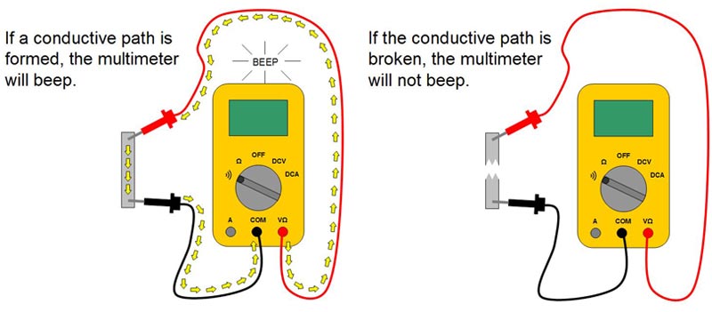
You will need a multimeter/DVOM to measure voltage and t-pins because you don't want to ruin the connector.

found this on another Honda forum

HondatechAV6 from www.superhonda.com

not fun...it's located behind the front cylinder head cam gear, bolted to the back of the bracket.
f_untitledm_b16c828.jpg

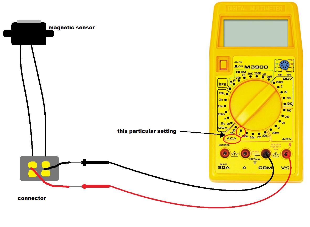
(if) They are magnetic sensors.

You can check for continuity.
sgtEuE9.jpg


You can also crank the engine and check for voltage. It should be around 100-600 ACmV.
64kCYbK.jpg
 
Last edited:

xci.ed6

Well-Known Member
Joined
Sep 5, 2007
Posts
2,909
Reaction score
9
Location
Tampa Bay
likely

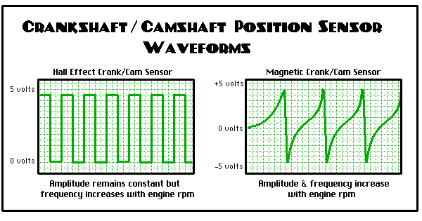
crank_waveform.gif


yours has a 'missing' or 'extra' tooth to indicate tdc.

I would guesstimate that if yours has power (either 5v or 12v) and gnd to the sensor and signal to the ecu, replace the sensor, then dig in deeper.
 

CDsDontBurn

Well-Known Member
Joined
Jan 8, 2010
Posts
1,859
Reaction score
29
Location
Where rusted out cars don't exist
You will need a multimeter/DVOM to measure voltage and t-pins because you don't want to ruin the connector.

found this on another Honda forum


(if) They are magnetic sensors.

You can check for continuity.
sgtEuE9.jpg


You can also crank the engine and check for voltage. It should be around 100-600 ACmV.
64kCYbK.jpg

It looks like I'll need to remove the timing belt cover to get to this area? If so, how is that done? Like, how far into this would I need to get into before I even have access to the TDC sensors for removal / replacement (presuming that is what's needed)? And based on this, it looks like I can just do the troubleshooting from the connector and not actually need to get to the sensor itself. Right?

pwr may not be reqd to sensor, you have yet to post a diagram

I haven't posted a diagram? Or who are you asking here?
 
Last edited:

chaby_91

Well-Known Member
Joined
Apr 21, 2010
Posts
585
Reaction score
4
Location
Montreal
It looks like I'll need to remove the timing belt cover to get to this area? If so, how is that done? Like, how far into this would I need to get into before I even have access to the TDC sensors for removal / replacement (presuming that is what's needed)? And based on this, it looks like I can just do the troubleshooting from the connector and not actually need to get to the sensor itself. Right?


I haven't posted a diagram? Or who are you asking here?

Do the testing first to see if that's the problem because although very unlikely, it is possible that the circuit is open and your sensors are fine. Always do the troubleshooting at the connector.

Here is another picture of the area you'll be working on, but you'll need to get your hands in here, because I have never done this and I own a 4 cyl...
13s8201_e1102.png
 
Back
Top