RR's '99 coupe EX-L

Mikey

Well-Known Member
Joined
Jul 24, 2010
Posts
3,362
Reaction score
28
Location
Middle America
Re: RR's 3.2L '99 EX-L Coupe 6MT

I thought the same thing about the A-Specs! :lol: 
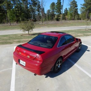
I was like, "Poor things. I'll come rescue you!"

Chris, is a red led strip out of the question? Or perhaps a light bar from an Acura or other high end vehicle?

As for my seat, IDK. Lol. When I ride in the passenger seat I feel lower. The driver seat is all the way down but I find myself slinking down to feel "lower"(insert joke about lowering my car here).
 

RedRyder

Save the manuals
Joined
Sep 5, 2008
Posts
19,516
Reaction score
118
Location
Fawking, OH
Re: RR's 3.2L '99 EX-L Coupe 6MT

^I'm using a highmount brakelight out of a 3G TL. See previous page ma nilla

Its much easier to run your own heated seat circuit, than trying to incorporate the CL one into the Accord. You Have the heated Canadian bezel, the Heated seats you just need the power. Before my Dash swap I ran it like this....

picture.php


From the drivers fuse box, there is empty slots that are only on when the car is on. This is great just incase you leave the button on you wont drain your battery. The red dot next to the driver is the relay.
The wire coming from the fuse box goes here. To the appropriate terminal.
Also another wire Directly from the battery to the relay with an inline fuse.

From there i Ran it to the switches. (Power wire from battery to relay to switch)
From the shifter console you can light the switches and ground them.

From the switches I passed the wire thru the center console down to the seats and wired it to the correct wires.

Its Simple dont look at it like a mission.

There is more steps not mentioned, but just so you get an idea.

By the way that Cream and red looks good.

THEM PHOTO EDITING SKILLS ARE GREAT HUH? LOL

Very good editing skills lol.

I know you know wiring, I appreciate the reply. So, I kind of understand, but there are still many holes here to fill in. It may be simple to you, but to me it is not and I'm sure it can be attributed to my lack of understanding of fuses, relays, etc. I've been wanting to look up articles/videos on basic wiring principles but since having my daughter it's been the furthest thing from my mind. I want to get back to this though, was hoping to have it done by winter.

Tell me if I am understanding this correctly. So one wire goes from the driver side fusebox to the relay (what amperage relay do I need?). What's the terminal you mentioned? And a second wire goes from the battery to an inline fuse (same amperage as relay?), then to the relay?

Sounds like from the relay I continue to run the power wire to the switches. I power whatever wire is for the switch itself, then power the switch bulbs and ground them using wires already in the console area (like cigarette lighter power wire?).

Then you say one wire goes from the switches to each seat...but the pigtails for both the switches and seat have multiple wires. I don't care about the seat memory function, just want to power the motors and heating elements. What I'm saying is it seems like a couple wires need to go from the switches to the seats...

Sorry, this is one area with working on cars I just do not have a grasp on. So I can admit I need it spelled out which is why it's taking me so long to understand what I need to do. Don't feel obligated to do so lol, I'm just saying.

I'm starting to envy your seats upgrade, as the weather starts to get colder nowadays... GL w/ the wiring!

So, do you need a resister for the 3rd brake light being LEDs? (Not seeing "brake light" on your gage cluster w/ this mod?)


Well, hello there A-spec. Looking fwd to see you in winter mode. (Really miss your GM A-Spec on the SMR.)

I've long had the brake light warning lamp on in my cluster for some time, pretty numb to it now. :lawl: It came on when I put LED bulbs in the tails, and I didn't like the idea of load resistors. Not sure if you need one for the 3rd brakelight only, maybe you do if the resistor was built in to the factory spoiler LED light.
 
Last edited:

Igor

Under construction
Joined
Nov 16, 2013
Posts
384
Reaction score
0
Location
Florida
Re: RR's 3.2L '99 EX-L Coupe 6MT

That brake light looking good!
 

Sil2DrV6

Well-Known Member
Joined
Oct 15, 2012
Posts
1,802
Reaction score
51
Location
USA
Re: RR's 3.2L '99 EX-L Coupe 6MT

I've long had the brake light warning lamp on in my cluster for some time, pretty numb to it now. :lawl: It came on when I put LED bulbs in the tails, and I didn't like the idea of load resistors. Not sure if you need one for the 3rd brakelight only, maybe you do if the resistor was built in to the factory spoiler LED light.
Same here lol. ← My SRS light has been on over an year or two b/c of my aged seat belt. It's beyond laziness, I must say. :lawl:
 

FNCONE

Well-Known Member
Joined
Feb 8, 2013
Posts
364
Reaction score
14
Location
NYC
Re: RR's 3.2L '99 EX-L Coupe 6MT

^

Very good editing skills lol.

I know you know wiring, I appreciate the reply. So, I kind of understand, but there are still many holes here to fill in. It may be simple to you, but to me it is not and I'm sure it can be attributed to my lack of understanding of fuses, relays, etc. I've been wanting to look up articles/videos on basic wiring principles but since having my daughter it's been the furthest thing from my mind. I want to get back to this though, was hoping to have it done by winter.

Tell me if I am understanding this correctly. So one wire goes from the driver side fusebox to the relay (what amperage relay do I need?). What's the terminal you mentioned? And a second wire goes from the battery to an inline fuse (same amperage as relay?), then to the relay?

Sounds like from the relay I continue to run the power wire to the switches. I power whatever wire is for the switch itself, then power the switch bulbs and ground them using wires already in the console area (like cigarette lighter power wire?).

Then you say one wire goes from the switches to each seat...but the pigtails for both the switches and seat have multiple wires. I don't care about the seat memory function, just want to power the motors and heating elements. What I'm saying is it seems like a couple wires need to go from the switches to the seats...

Sorry, this is one area with working on cars I just do not have a grasp on. So I can admit I need it spelled out which is why it's taking me so long to understand what I need to do. Don't feel obligated to do so lol, I'm just saying.

I totally understand. Just as if I where to try something in your line of work, I would be lost. Tomorrow I'am off. I will check my accord harness and pull the one I made out and ship it to you. Not Rywire Quality but it works!!! LOL. Shipping is your problem. :)

Lets see if I can explain it,

picture.php


1. The Drivers fuse box has empty slots that have power. Which I believe 2 are only on when the car is on. Which is great for not draining your battery.
Where the pencil is pointing, are the slots on the drivers fuse box that I'am talking about. ( Under The Steering wheel, NOT the side with the fuses).
We will use 2 slots. Preferably the ones that have no power when the car is off.


** I Do Not Know Why The Picture Is Upside Down. Its Suppose To Be With The Pencil On The lower Left Corner**

2. 1 of the slots will have a 7.5A Inline fuse. The other slot will use a 20A Inline fuse.

3. You will need a 4 pin relay.

3A. The wire that has the 7.5A will go to connector 86 on the relay.

3B. The wire with the 20A will go to connector 30 on the relay.

3C. Connector 85 From the relay goes to any good ground.

ALL THIS IS JUST UP TO THE RELAY (THE RED DOT IN MY AWESOME EDITED PICTURE)

3D. Pin 87 on the relay now travels all the way to the switches.

4. Each switch has a WHITE/BLACK wire splice them together and splice it into the wire coming from the relay pin 87.

5. Each Switch has 6 wires. (5 left since we spliced the WHITE/BLACK one In step 4.

5A. Ground both black wires from both switches to the frame, or with the radio black wire. (Any ground is fine)

5B. There is a RED and RED/BLACK wire on each switch. Splice them together and splice into the radio RED and RED/BLACK wires accordingly.

ALL UP TO HERE ARE THE 2 RED DOTS WHERE THE CANADIAN SWITCHES GO

6A. The drivers switch has 2 wires left. Usually the one with red is high and blue is low. For example, WHITE/RED is the high, WHITE/BLUE is the low setting. Run each wire to the appropriate Pin-out on your seat of choice. (Depending on your model seat, the Pin-Out Changes for different year models) Just let me know what year CL seat you Have.

6B. SAME THING ON THE PASSENGERS SIDE

7. GROUND THE CORRECT GROUND WIRES FROM THE SEAT CONNECTOR. If you don't, the circuit will be incomplete and wont work. If you want to test them, Sit on them. LOL DUH, But I mean sit on them because when I had my 03 Accord seats in my car, they have some type of sensor that only works when someone is sitting on them. I hated that. I'am not sure how the Acura ones are setup.

I don't need it. If you want pay for the relay (not sure where mine went) and shipping and you can have it. Here it is......Not the prettiest but its in perfect working order.


After The Inline Fuses You Can See Some Small Cut Wires, This is where The relay Use to be.


:grd:
 
Last edited:

Sil2DrV6

Well-Known Member
Joined
Oct 15, 2012
Posts
1,802
Reaction score
51
Location
USA
Re: RR's 3.2L '99 EX-L Coupe 6MT

Don't mean to bother you two, but I just had to say this...

^ How the hell you figure out all of that?? Sounds like my social security will expire by the time I'm done w/ those work on my own...
 

FNCONE

Well-Known Member
Joined
Feb 8, 2013
Posts
364
Reaction score
14
Location
NYC
Re: RR's 3.2L '99 EX-L Coupe 6MT

Don't mean to bother you two, but I just had to say this...

^ How the hell you figure out all of that?? Sounds like my social security will expire by the time I'm done w/ those work on my own...

Lmao Social Security...

I just took the Alldata diagram and made the circuit. In the Canadian model the wires travel from the engine bay all the way thru passengers side connecting at multiple connectors. I just made the run shorter and simpler. I found those empty slots when I was doing my car navigation. I didn't want to run power from the battery (which I eventually had to lol) and I found those empty slots and tested them. 45 minutes tops, simple circuit. Let me know if you need help.
 

FNCONE

Well-Known Member
Joined
Feb 8, 2013
Posts
364
Reaction score
14
Location
NYC
Re: RR's 3.2L '99 EX-L Coupe 6MT

I just saw you have the 6 speed seats. They only have 1 setting. No high and low.
 

RedRyder

Save the manuals
Joined
Sep 5, 2008
Posts
19,516
Reaction score
118
Location
Fawking, OH
Re: RR's 3.2L '99 EX-L Coupe 6MT

I totally understand. Just as if I where to try something in your line of work, I would be lost. Tomorrow I'am off. I will check my accord harness and pull the one I made out and ship it to you. Not Rywire Quality but it works!!! LOL. Shipping is your problem. :)

Lets see if I can explain it,

http://www.6thgenaccord.com/forums/picture.php?albumid=1207&pictureid=6927[IMG]


1. The Drivers fuse box has empty slots that have power. Which I believe 2 are only on when the car is on. Which is great for not draining your battery.
Where the pencil is pointing, are the slots on the drivers fuse box that I'am talking about. ( Under The Steering wheel, NOT the side with the fuses).
We will use 2 slots. Preferably the ones that have no power when the car is off.

[URL=http://s37.photobucket.com/user/FNCONE/media/AccordDriversFuseBox2001V6.jpg.html][IMG]http://i37.photobucket.com/albums/e63/FNCONE/AccordDriversFuseBox2001V6.jpg~original[IMG][/URL]

** I Do Not Know Why The Picture Is Upside Down. Its Suppose To Be With The Pencil On The lower Left Corner**

2. 1 of the slots will have a 7.5A Inline fuse. The other slot will use a 20A Inline fuse.

3. You will need a 4 pin relay.

3A. The wire that has the 7.5A will go to connector 86 on the relay.

3B. The wire with the 20A will go to connector 30 on the relay.

3C. Connector 85 From the relay goes to any good ground.

[B]ALL THIS IS JUST UP TO THE RELAY (THE RED DOT IN MY AWESOME EDITED PICTURE)
[/B]
3D. Pin 87 on the relay now travels all the way to the switches.

4. Each switch has a WHITE/BLACK wire splice them together and splice it into the wire coming from the relay pin 87.

5. Each Switch has 6 wires. (5 left since we spliced the WHITE/BLACK one In step 4.

5A. Ground both black wires from both switches to the frame, or with the radio black wire. (Any ground is fine)

5B. There is a RED and RED/BLACK wire on each switch. Splice them together and splice into the radio RED and RED/BLACK wires accordingly.

[B]ALL UP TO HERE ARE THE 2 RED DOTS WHERE THE CANADIAN SWITCHES GO[/B]

6A. The drivers switch has 2 wires left. Usually the one with red is high and blue is low. For example, WHITE/RED is the high, WHITE/BLUE is the low setting. Run each wire to the appropriate Pin-out on your seat of choice. (Depending on your model seat, the Pin-Out Changes for different year models) Just let me know what year CL seat you Have.

6B. SAME THING ON THE PASSENGERS SIDE

7. GROUND THE CORRECT GROUND WIRES FROM THE SEAT CONNECTOR. If you don't, the circuit will be incomplete and wont work. If you want to test them, Sit on them. LOL DUH, But I mean sit on them because when I had my 03 Accord seats in my car, they have some type of sensor that only works when someone is sitting on them. I hated that. I'am not sure how the Acura ones are setup.

I don't need it. If you want pay for the relay (not sure where mine went) and shipping and you can have it. Here it is......Not the prettiest but its in perfect working order.

[URL=http://s37.photobucket.com/user/FNCONE/media/DIYHeatedCircuit.jpg.html][IMG]http://i37.photobucket.com/albums/e63/FNCONE/DIYHeatedCircuit.jpg~original[IMG][/URL]


[URL=http://s37.photobucket.com/user/FNCONE/media/DIYHeatedCircuitEdited.jpg.html][IMG]http://i37.photobucket.com/albums/e63/FNCONE/DIYHeatedCircuitEdited.jpg~original[IMG][/URL]

After The Inline Fuses You Can See Some Small Cut Wires, This is where The relay Use to be.


:grd:[/quote]

Whoa...you went above and beyond, thanks a lot! I know I’ll be reading that repeatedly (already have). I had begun to understand which wires from the seat were for what, and the basics of what I need to do overall, but that’s as far as I got. This is awesome , repped.

I feel guilty at the thought of taking the harness you made, but if you are indeed offering it I am interested. Can you re-integrate a relay if I pay you for it? Happy to pay for shipping of course.

Btw the seats are from 2003 6MT.


EDIT:

[quote="FNCONE, post: 1060345"]I just saw you have the 6 speed seats. They only have 1 setting. No high and low.[/quote]

Strange. So the autos have high and low settings and the manual doesn't? It just has high, I assume...

The Canadian switches have a high and low setting...guess they will only work when I push them one way or the other then?
 
Last edited:

FNCONE

Well-Known Member
Joined
Feb 8, 2013
Posts
364
Reaction score
14
Location
NYC
Re: RR's 3.2L '99 EX-L Coupe 6MT

I would recommend just using the high. If we splice them together both wires will be live. Technically shouldn't do harm in a Direct current scenario, but just to be on the safe side I would just keep 1 side working. (The High ).

Yes the 6 speed CL seats only have 1 setting. Have you ever seen the console for the Manual CL? The buttons for the seats are by the armrest in the center console. Not by the cubby. There is only 2 buttons drivers and passengers. No high and lows.

I'll add the relay asap.
LOL don't worry about it. I don't need it anymore. Its Not Like its a Rywire or Chasebay Harness lol.
 
Last edited:
Back
Top