

The title says it all, I'm going to make sure my butt stays warm during the colder days and nights.  This thread is a work in progress. I am not done installing it yet. You will notice that this could be a cleaner job, but making connectors is not the most important thing right now.
OK so the first thing to do was figure out the electrical diagram. The problem was that the accord seat heater has 2 heat levels while the RSX only have one. That not really a problem tho. you just to connect one of the wires and it going to work. But I wanted to have both settings working from the Accord switches. So I was lucky enough to find the electrical diagram from both cars. and was able to figure out a way plug them in.
This wiring diagram shows where I am at the moment. it's pretty self explanatory if you know what you're looking at.
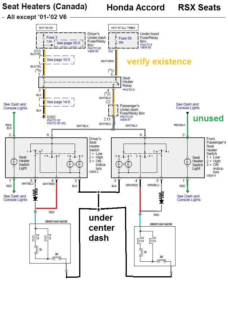
I added a resistance and a diode to the low setting to lower the voltage and make sure I don't short out the circuit everytime I use low setting. I had never built a custom circuit before so I didn't know what type of resistors to use. I just know it theorically had to be 0.6Ω. So I went to the local electronic store to get some help. I explained to the electronics guru guy what I wanted to do and we looked at the diagram. This is the final montage v1.0
He also said heat would be a concern and I should keep these in a ventilated area. I'm not going to do that so I need to know how hot these things will get. They are 25W 3Ω 6J. That's a total of 75W 1Ω* 18J.
*because of parallel connection
I'm going to skip you the math, but this means that these little bricks will produce enough heat to raise their temp by 2.27 °C every minute. I'm not sure what I'm going to do about that.
I also know that there are heat switches in the heater's circuit. If I'm lucky, these switches alone will keep the resistor box from getting too hot.
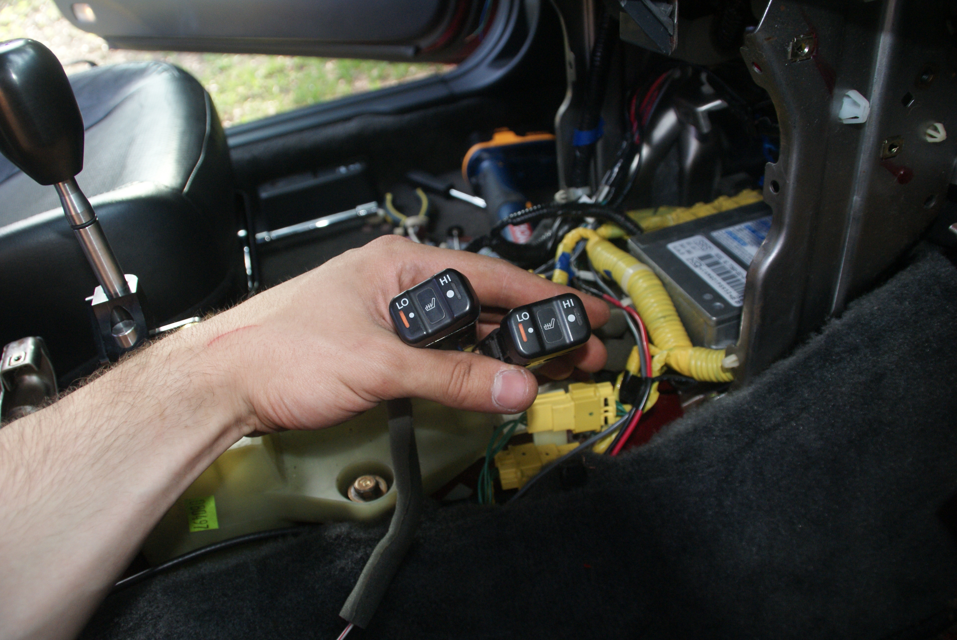
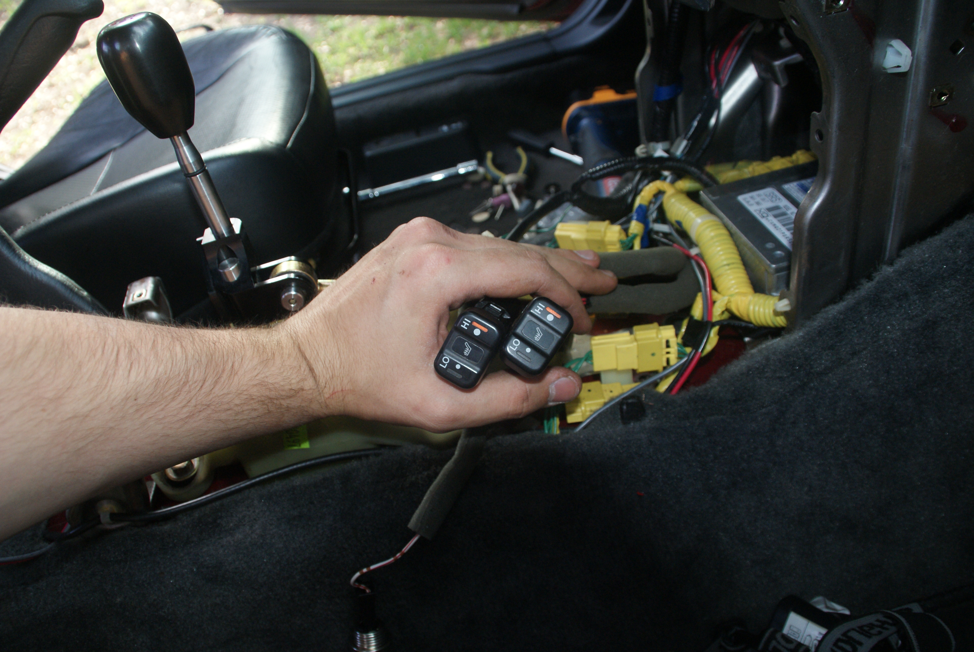
Anyway, here is where I passed the wires under the carpet. It's the same on the other side.
This is the ground I used for practicality reasons. You can also kind of see that all my wires follow the existing harness. No random loose wires is best.
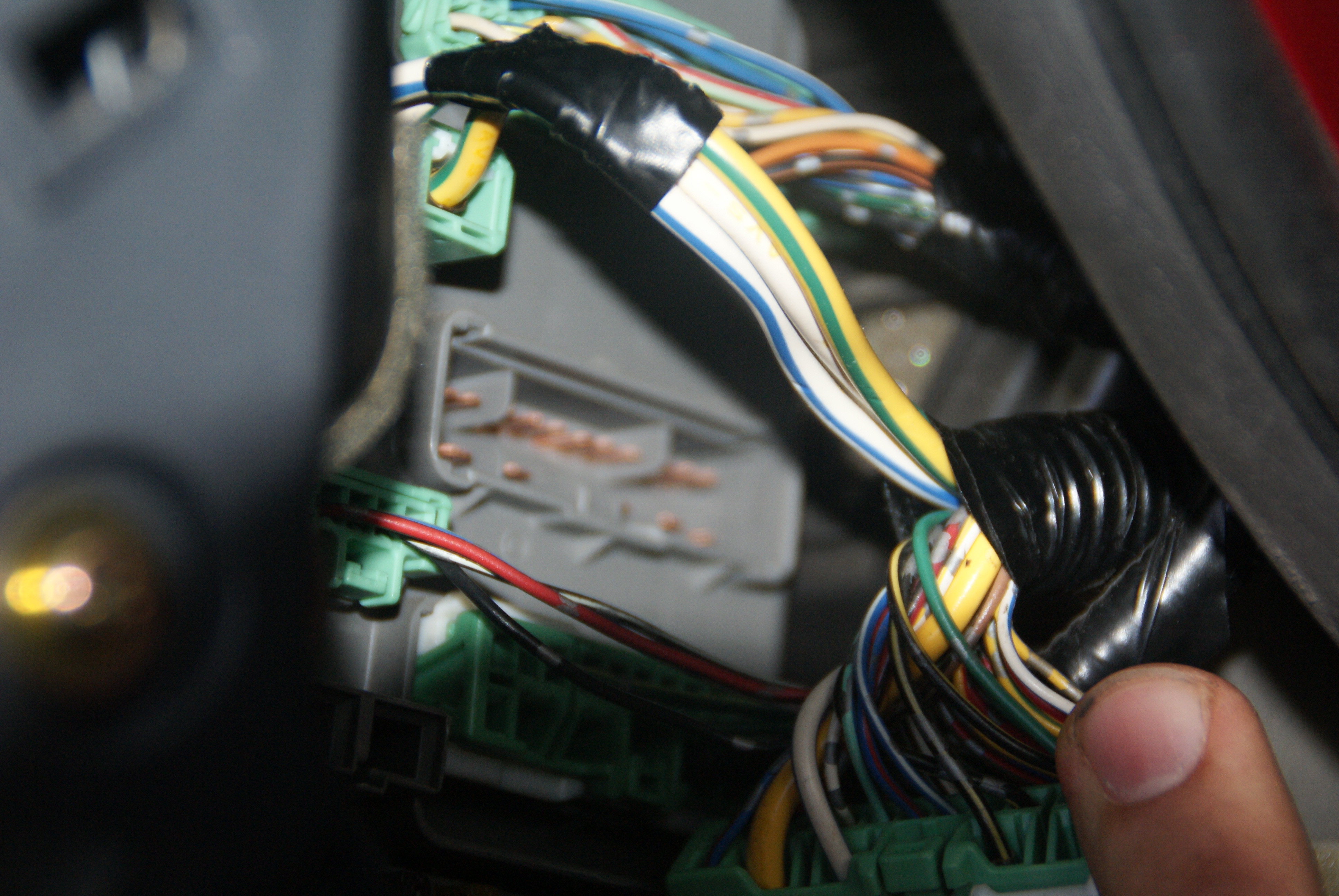
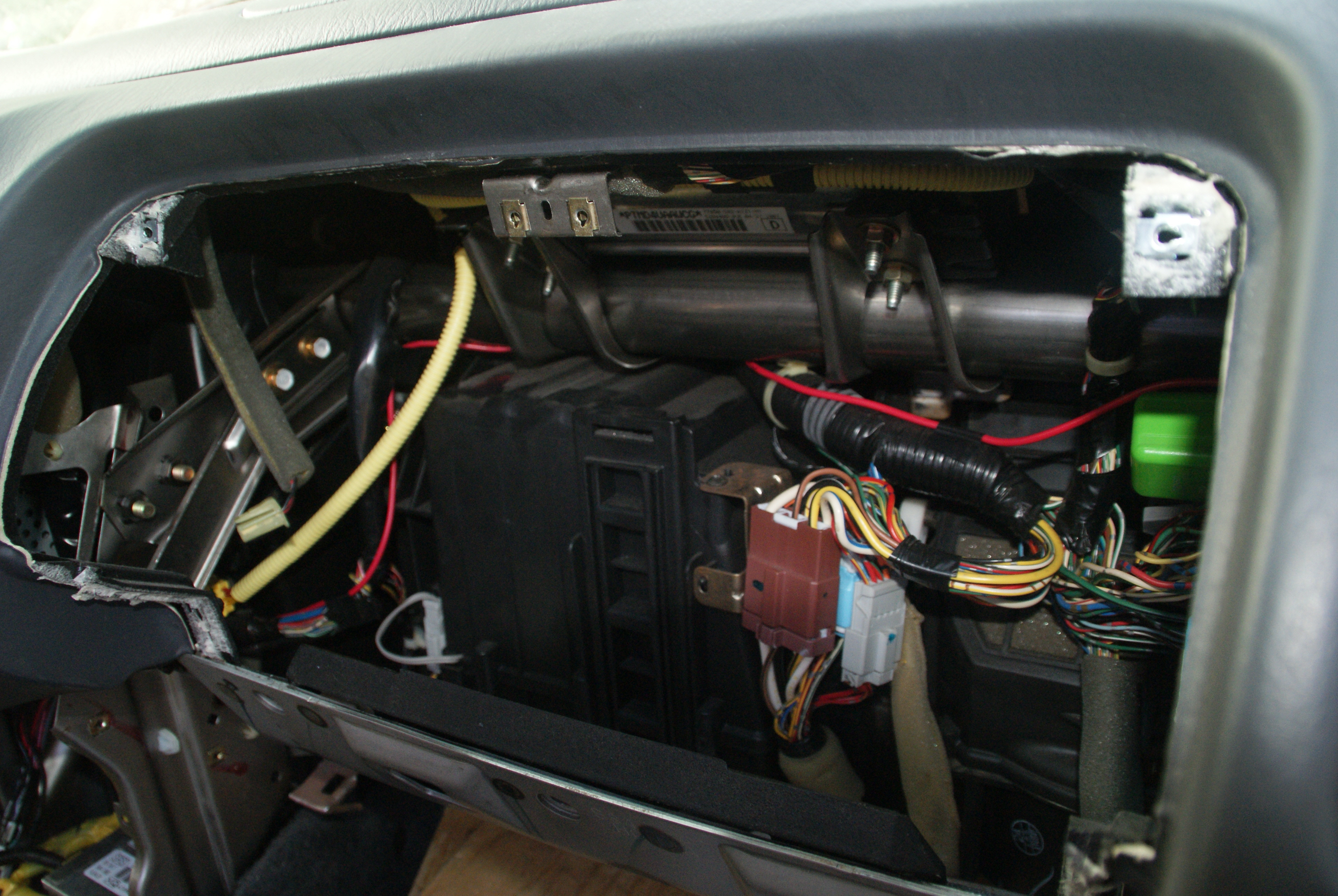
Wires go over the steering column, following an existing harness up to this empty space under the driver side dash where I'm putting the resistor box.
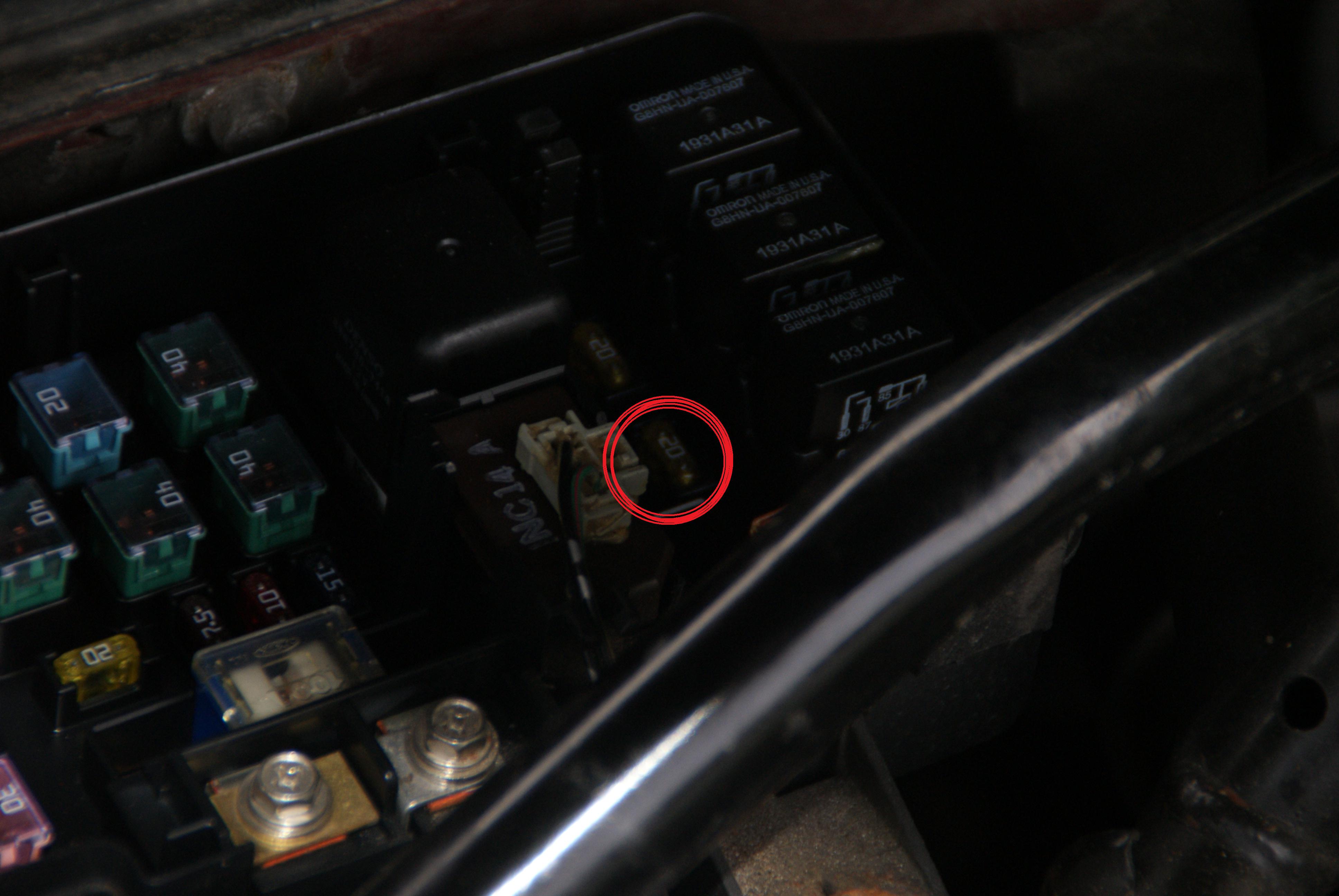
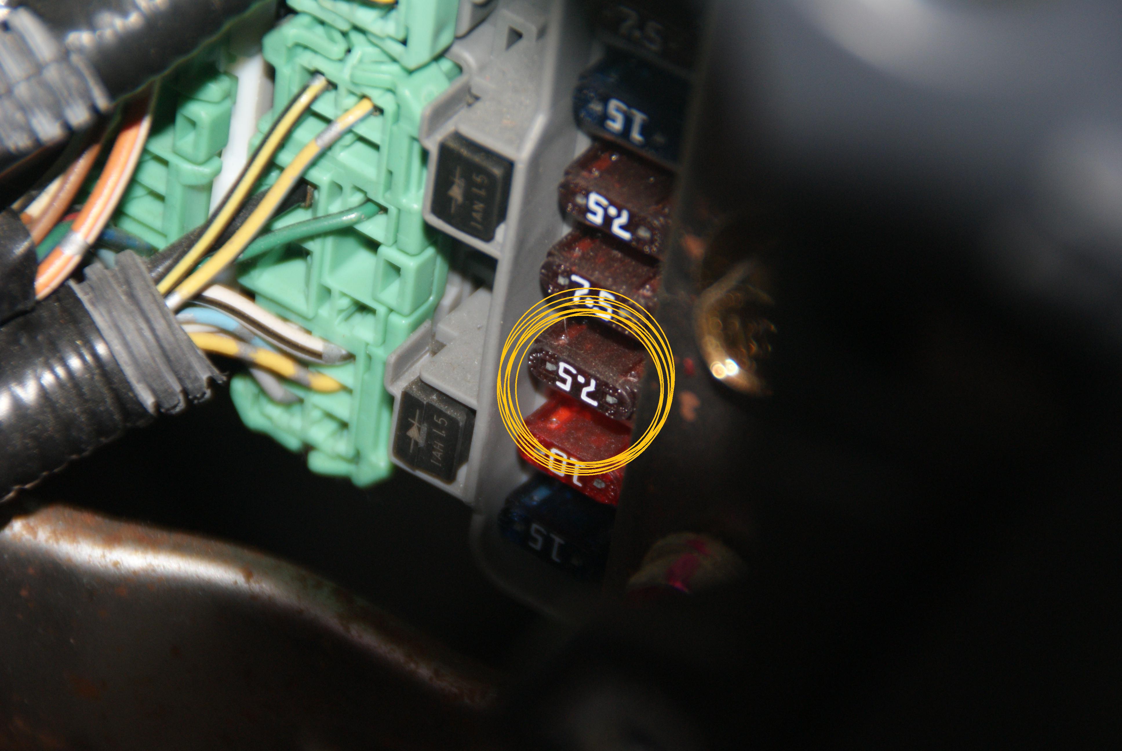
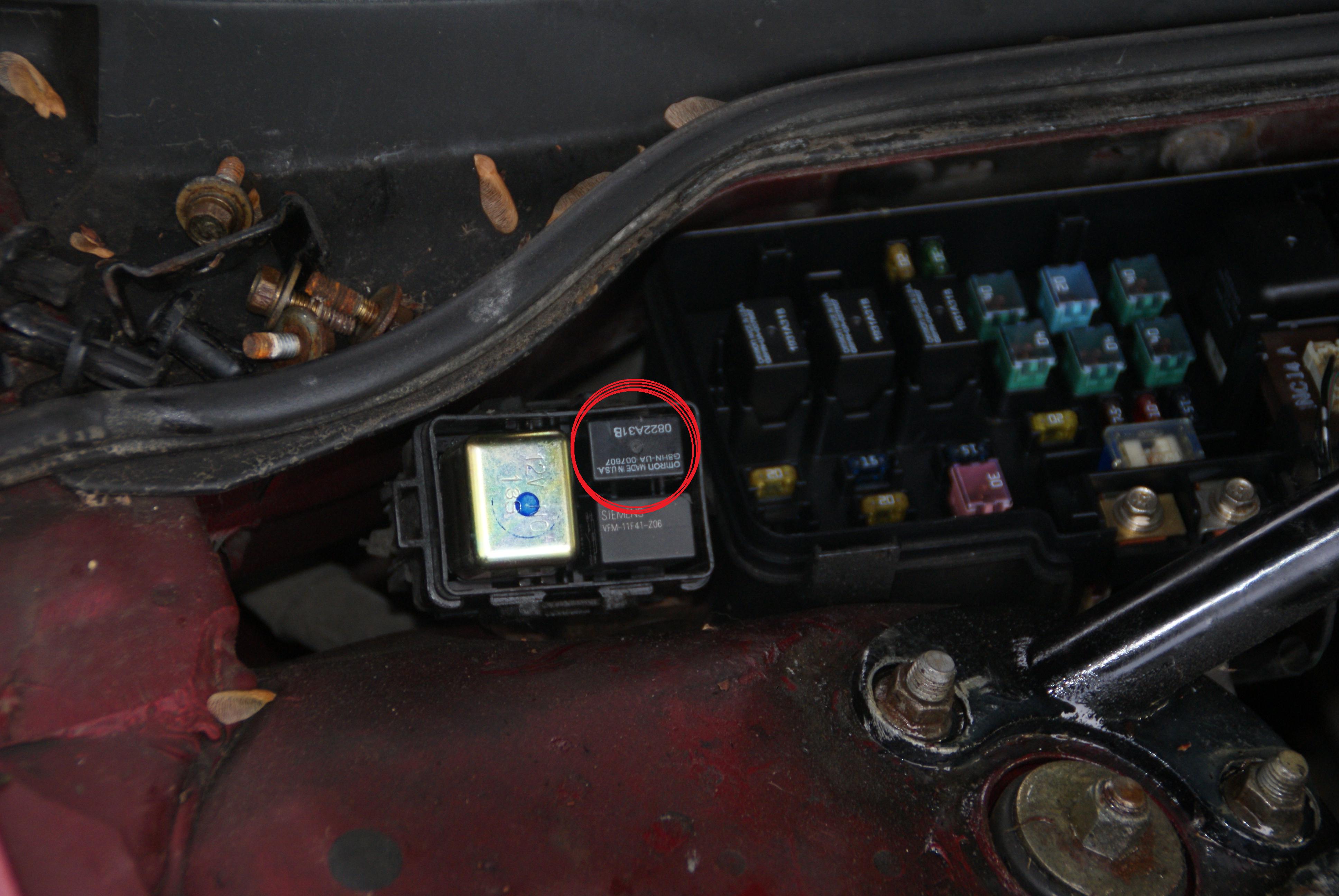
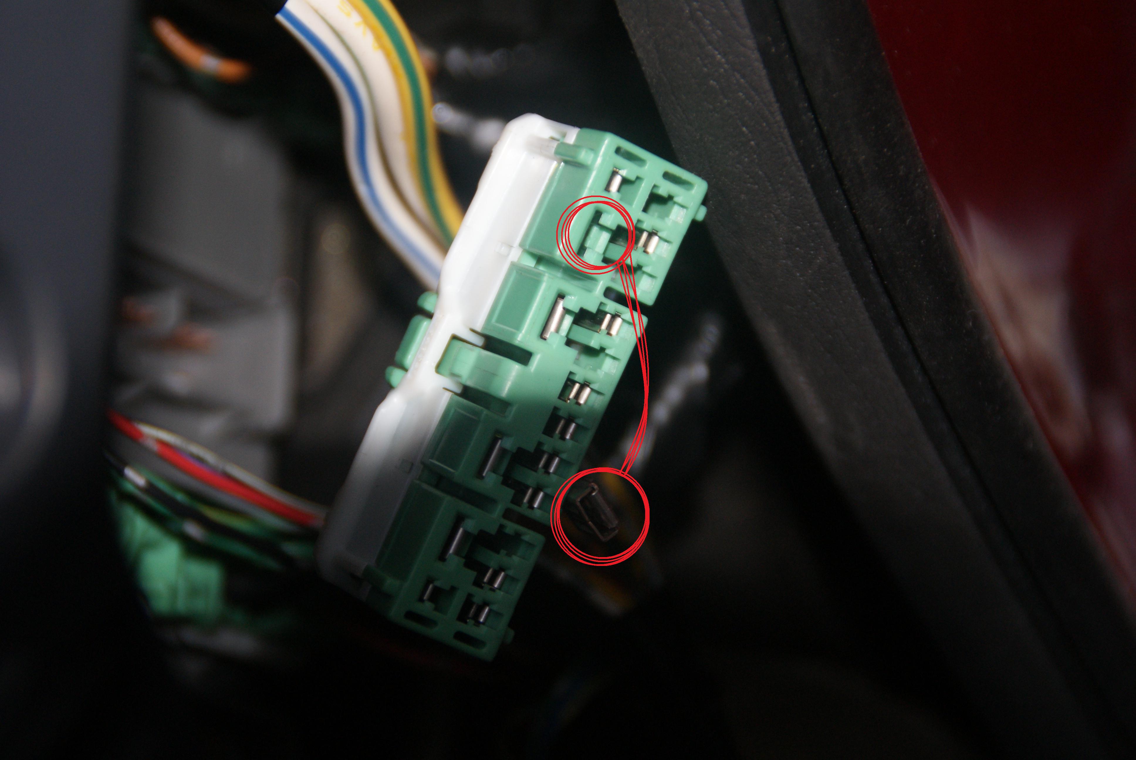
This is where I am right now. I still need to make sure the factory wiring exist, then put relay and fuses in and get power to the switches.
This thread is a work in progress. I am not done installing it yet. You will notice that this could be a cleaner job, but making connectors is not the most important thing right now.OK so the first thing to do was figure out the electrical diagram. The problem was that the accord seat heater has 2 heat levels while the RSX only have one. That not really a problem tho. you just to connect one of the wires and it going to work. But I wanted to have both settings working from the Accord switches. So I was lucky enough to find the electrical diagram from both cars. and was able to figure out a way plug them in.
This wiring diagram shows where I am at the moment. it's pretty self explanatory if you know what you're looking at.
I added a resistance and a diode to the low setting to lower the voltage and make sure I don't short out the circuit everytime I use low setting. I had never built a custom circuit before so I didn't know what type of resistors to use. I just know it theorically had to be 0.6Ω. So I went to the local electronic store to get some help. I explained to the electronics guru guy what I wanted to do and we looked at the diagram. This is the final montage v1.0
He also said heat would be a concern and I should keep these in a ventilated area. I'm not going to do that so I need to know how hot these things will get. They are 25W 3Ω 6J. That's a total of 75W 1Ω* 18J.
*because of parallel connection
I'm going to skip you the math, but this means that these little bricks will produce enough heat to raise their temp by 2.27 °C every minute. I'm not sure what I'm going to do about that.
I also know that there are heat switches in the heater's circuit. If I'm lucky, these switches alone will keep the resistor box from getting too hot.
Anyway, here is where I passed the wires under the carpet. It's the same on the other side.
This is the ground I used for practicality reasons. You can also kind of see that all my wires follow the existing harness. No random loose wires is best.
Wires go over the steering column, following an existing harness up to this empty space under the driver side dash where I'm putting the resistor box.
This is where I am right now. I still need to make sure the factory wiring exist, then put relay and fuses in and get power to the switches.
Last edited: