

9450erick
Well-Known Member
Dont forget to cover any bear wiring or spices with electrical tape
Have to use M.T. computer
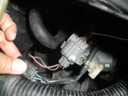
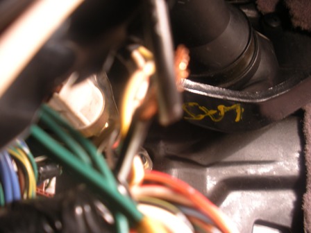
1)Locate the Blue and green wire that originally was your speedometer sensor
its under the hood, behind the transmission, next to the firewall, really close to the big tranny plug
2) take off the panells below the steering wheel and the glove box
3) take off the glove box
http://syclone.motocrew.com/CG5/acfilter.htm
4) locate your ecu
5) disconnect the blue connector(31P) and the small auto connector (16P)(the smallest connector on the ecu) from the ecu
6)The blue and green wire, that you located in step 1, connect directly to the small auto connector. 1st find the blue wire on the small connector, it will be in the middle row third wire in from the right.(this will be your signal wire)
7) once you think you found it, you have to make sure you found the right wire 7a) with a exacto knife cut the rubber protectant off to expose the copper inside(dont cut all the way through the wire)(dont cut to close to the end of the wire just in case you do cut through the wire you still have some wire to play with)
8)Check for continuity with the wire under the hood. It should have continuity.
9) PLEASE MAKE SURE YOU CHECK FOR CONTINUITY. THERE ARE LIKE 4 BLUE WIRES IN THAT SAME CONNECTOR
10)The green wire that located in step 1 will be your ground and this wire is directly above the blue wire in the small auto connector
11)Now you have to depin which is a b**ch. You only need to depin the blue wire but if you F**K up the pin u can always depin the green wire. You do not need the pin from the green wire
12)With a really small flathead screw driver, be very careful, pull on the white lock on top of the connector, it will only come up a little bit. With this lock up pull the wire out with a pair of needle nose pliers very carefully. It may take a good steady pull. (While you pull with the pliers it helps if you jam the little flathead on the other side and push on it.)(that might mess up the pin)
13)Now you have to repin the blue wire into the blue connector. the pin goes all the way to the bottom left
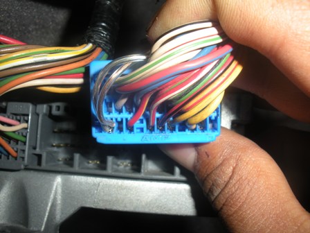
Once again pull up on the lock on top of the connector. Once the lock is up push the wire firmly in till it bottoms out, you may feel it kind of click in there. While your still pushing it in push the lock back down. There you have just re-pinned a connector.
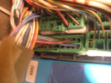
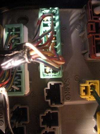
14)Now you need to locate the backside of the passenger fuse box(it where the glove box used to be) there are 4 green connectors. the green connector you need is a 18pin located left,bottom((has a blue/white wire and on top of that a green wire)
(its the connector closest to the white sticker that say 8882 in the pic)
15)cut into the blue/white wire (all the way on the right bottom of the connector you found in step 14) as directed in step 7a. you do not need to check for continuity in this wire
16)you are going to have to run an extra wire that connects both the blue wire that you repinned and this blue/white wire. as long as they are touching they are fine. i spliced mine with the pin but u can put it anywhere
17)The green wire is your ground so you can ground it anywhere u like. i put mine on the 10mm bolt (bottom right)just below the glove box
18) Now go to the driver side. get underneath the steering wheel and face the door. now look up and you have found the back side of the driver side fuse box
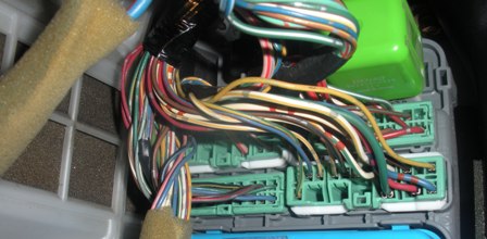
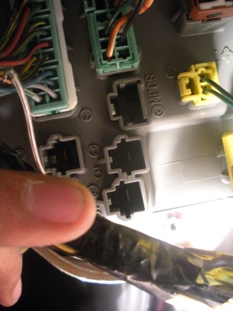
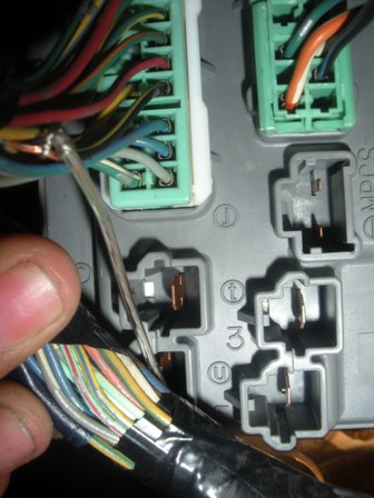
19) locate a green 18pin connector. there are 3 of theses. its the 1 furthest left.
this is the 1 you r looking for
(its the 1 all the way to the left of this pic)
20)now that you have found this connector locate the black/yellow (not yellow/black)wire. its right next to the red/black wire
21) cut as directed in 7a
22) connect 3 feet of wiring to it
23)you are going to have to take that 3 feet of wiring into the engine bay, so as long as you get it close to the blue and green wires doesnt matter how you get it there
24) Still on the drivers side of the dash locate the black/white wire on the ignition switch harness. It will be in a brown plug and a fairly good size wire.(its way at the top of the connector)(its not White/black) The other wire you need is also a black/white wire. This will be located on the back side of the driver side fuse box. I will be in a green 7 pin connector.(this 1 is @ the bottom of the connector) There will only be 4 wires it. You want the black/white wire. Cut both these wires and connect the two ends that are no connected to the fuse box(so there should be 2 wires sticking out of the fuse box make sure u cover these up as well with electrical tape)solder together.
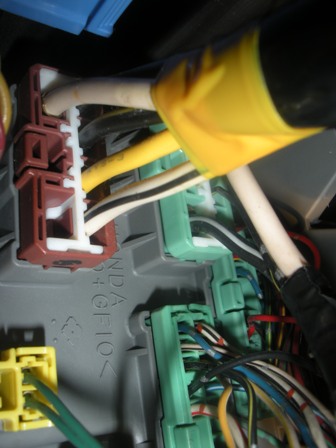
(both connectors are shown in this pic they are side by side)(the top 2)
it should look like this(the two black/white wires connected in the center of the pic next to the yellow writing)
25)Go to the engine bay. locate the vss pigtail. its way behind the tranny. You can probably barely see it if you angle yourself right. just feel around the back of your transmission. it should have 3 wires sticking out.
26)1st wire is ground-Connect that to the green wire
2nd wire is power-Connect that to the 3 feet of wire you extended
3rd wire is signal- Connect that to the blue wire
27) (Dont forget your radio code)disconnect the negative terminal and wait for 15sec or a lil more so the ecu can reset.
27) if it does not work it might be your vss.
28) if it does like mine did(thank god) enjoy the smooth pick up around 4K rpm when v-tec hits. it F**ken unbelievable.
ohh and watch the speedo, now that you can lol
if this works, dont forget to rep. i asked for like month and nobody knew how to do it. this is the 1st DIY of the speedo install that actually works and isnt hard to understand
if it doesnt pm me and ill try to help
Have to use M.T. computer
1)Locate the Blue and green wire that originally was your speedometer sensor
its under the hood, behind the transmission, next to the firewall, really close to the big tranny plug
2) take off the panells below the steering wheel and the glove box
3) take off the glove box
http://syclone.motocrew.com/CG5/acfilter.htm
4) locate your ecu
5) disconnect the blue connector(31P) and the small auto connector (16P)(the smallest connector on the ecu) from the ecu
6)The blue and green wire, that you located in step 1, connect directly to the small auto connector. 1st find the blue wire on the small connector, it will be in the middle row third wire in from the right.(this will be your signal wire)
7) once you think you found it, you have to make sure you found the right wire 7a) with a exacto knife cut the rubber protectant off to expose the copper inside(dont cut all the way through the wire)(dont cut to close to the end of the wire just in case you do cut through the wire you still have some wire to play with)
8)Check for continuity with the wire under the hood. It should have continuity.
9) PLEASE MAKE SURE YOU CHECK FOR CONTINUITY. THERE ARE LIKE 4 BLUE WIRES IN THAT SAME CONNECTOR
10)The green wire that located in step 1 will be your ground and this wire is directly above the blue wire in the small auto connector
11)Now you have to depin which is a b**ch. You only need to depin the blue wire but if you F**K up the pin u can always depin the green wire. You do not need the pin from the green wire
12)With a really small flathead screw driver, be very careful, pull on the white lock on top of the connector, it will only come up a little bit. With this lock up pull the wire out with a pair of needle nose pliers very carefully. It may take a good steady pull. (While you pull with the pliers it helps if you jam the little flathead on the other side and push on it.)(that might mess up the pin)
13)Now you have to repin the blue wire into the blue connector. the pin goes all the way to the bottom left
Once again pull up on the lock on top of the connector. Once the lock is up push the wire firmly in till it bottoms out, you may feel it kind of click in there. While your still pushing it in push the lock back down. There you have just re-pinned a connector.
14)Now you need to locate the backside of the passenger fuse box(it where the glove box used to be) there are 4 green connectors. the green connector you need is a 18pin located left,bottom((has a blue/white wire and on top of that a green wire)
(its the connector closest to the white sticker that say 8882 in the pic)
15)cut into the blue/white wire (all the way on the right bottom of the connector you found in step 14) as directed in step 7a. you do not need to check for continuity in this wire
16)you are going to have to run an extra wire that connects both the blue wire that you repinned and this blue/white wire. as long as they are touching they are fine. i spliced mine with the pin but u can put it anywhere
17)The green wire is your ground so you can ground it anywhere u like. i put mine on the 10mm bolt (bottom right)just below the glove box
18) Now go to the driver side. get underneath the steering wheel and face the door. now look up and you have found the back side of the driver side fuse box
19) locate a green 18pin connector. there are 3 of theses. its the 1 furthest left.
this is the 1 you r looking for
(its the 1 all the way to the left of this pic)
20)now that you have found this connector locate the black/yellow (not yellow/black)wire. its right next to the red/black wire
21) cut as directed in 7a
22) connect 3 feet of wiring to it
23)you are going to have to take that 3 feet of wiring into the engine bay, so as long as you get it close to the blue and green wires doesnt matter how you get it there
24) Still on the drivers side of the dash locate the black/white wire on the ignition switch harness. It will be in a brown plug and a fairly good size wire.(its way at the top of the connector)(its not White/black) The other wire you need is also a black/white wire. This will be located on the back side of the driver side fuse box. I will be in a green 7 pin connector.(this 1 is @ the bottom of the connector) There will only be 4 wires it. You want the black/white wire. Cut both these wires and connect the two ends that are no connected to the fuse box(so there should be 2 wires sticking out of the fuse box make sure u cover these up as well with electrical tape)solder together.
(both connectors are shown in this pic they are side by side)(the top 2)
it should look like this(the two black/white wires connected in the center of the pic next to the yellow writing)
25)Go to the engine bay. locate the vss pigtail. its way behind the tranny. You can probably barely see it if you angle yourself right. just feel around the back of your transmission. it should have 3 wires sticking out.
26)1st wire is ground-Connect that to the green wire
2nd wire is power-Connect that to the 3 feet of wire you extended
3rd wire is signal- Connect that to the blue wire
27) (Dont forget your radio code)disconnect the negative terminal and wait for 15sec or a lil more so the ecu can reset.
27) if it does not work it might be your vss.
28) if it does like mine did(thank god) enjoy the smooth pick up around 4K rpm when v-tec hits. it F**ken unbelievable.
ohh and watch the speedo, now that you can lol
if this works, dont forget to rep. i asked for like month and nobody knew how to do it. this is the 1st DIY of the speedo install that actually works and isnt hard to understand
if it doesnt pm me and ill try to help
Last edited:
 Luckily mine was 5-speed stock