

dorkiedoode
Well-Known Member
Hello guys this will be my first time installing an alarm and I will be tackling a Viper 5901. Frequently I read that people recommend taking it to the pro's but I'm on summer vacation with A LOT of free time on my hands so I took it upon myself to make projects to keep myself busy and productive. I love learning new things so I decided that it would be fun to learn how to install alarms. Note that I am not a PRO nor anywhere near it, but I do have BASIC electrical knowledge to install an alarm. Now supposedly the Viper 5901 is one of the hardest alarm to install and it comes with the worst instruction manual in the world! However, luckily our car is one of the easiest  . So I probably will not be able to answer all your questions (or any hard ones) LOL but this is how I did it and it works
  . Please if your not confident enough to install it then do take it to the pros. I am not responsible if you f'ed up your car!! It took me two days of research, a day on probing wires with a digital multimeter (DMM), and several hours to install. Actually, I'm still in the process of cleaning up the wires, mounting the antenna, installing a trunk relay, and bypass module. Here we go..might take me several days to finish it...I took pix of everything...kind of. Some of my method is not the best so I suggest you do your own research as well. Soldering the wires is recommended but some wires i just used t-taps because its a pain the in *** to get at... Will update this thread over time.. Writing this at 5:40AM so its messy...

Parts
Viper 5901
Digital MutliMeter
Transponder Bypass ( I am getting the one from Idatalink ADS-TBSL HA)
Soldering Iron
Electrical Tape
Wire Stripper and Crimper
Heat Shrink
Wiring Diagram
T-Taps
Wire Looms
Pliers
Loads of free time
Instruction Manual
(http://www.directeddealers.com/manuals/IG/Viper/N5702V_2008_08web.pdf)
STEP 1:
Research research research I can't stress that enough. here are some site that i used to help me understand it better.
1] 12volt.com ( I googled Honda Accord and read through 100 of pages lol)
2] http://forums.evolutionm.net/evo-audio-security/364122-diy-viper-5701-install-ct9a.html
3] http://causeforalarm.thecarthing.com/version6/stealth_alarm/ek_civic/index.html
4] http://www.acuraworld.com/forums/f72/very-detailed-install-viper-5901-remote-start-87562/
STEP 2:
1999 HONDA ACCORD EX-L V6 COUPE WITH FACTORY ALARM Wiring Diagram
There are several different versions that i found on the net. I actually used three different ones for different wires.
1. [http://www.the12volt.com/installbay/forum_posts.asp?TID=60729&KW=1999+accord+wiring
2. http://www.the12volt.com/installbay/forum_posts.asp?TID=99405&KW=python+accord
3. 12 volt diagram
STEP THREE:
PROBE YOUR WIRES!! MAKE SURE THEY ARE CORRECT.
STEP FOUR:
INSTALL
VIPER 5901
➢ Primary harness (H1), 12-pin connector
H1/1 RED/WHITE (-) 200mA TRUNK RELEASE OUTPUT
H1/2 RED (+)12v CONSTANT INPUT
H1/3 BROWN (+) SIREN OUTPUT
H1/4 WHITE/BROWN LIGHT FLASH ISOLATION WIRE - PIN 87a of onboard rel
H1/5 BLACK (-) CHASSIS GROUND
H1/6 VIOLET (+) DOOR TRIGGER INPUT
H1/7 BLUE (-) TRUNK PIN/ INSTANT TRIGGER INPUT
H1/8 GREEN (-) DOOR TRIGGER INPUT
H1/9 BLACK/WHITE (-) 200mA DOME LIGHT OUTPUT
H/10 WHITE/BLUE (-) REMOTE START/ TURBO TIMER ACTIVATION INPUT
H/11 WHITE PARKING LIGHT OUTPUT
H/12 ORANGE (-) 500mA GROUND WHEN ARMED OUTPUT
CAR WIRING FOR H1 HARNESS (pictures will be provided for wires that are not obvious. IF left blank, connection is not needed!)
PIN--------VEHICLE WIRE---------------LOCATION
H1/1--------WHITE/RED (+) ------------driver's kick panel, needs a relay! (http://www.the12volt.com/relays/relaydiagram8.html)
H1/2--------WHITE (+)-----------------at ignition switch or anywhere you can find a constant 12v
H1/3--------RED WIRE ON VIPER SIREN (+) --siren lead
H1/4
H1/5--------BLACK (-) -----------------anywhere you can find ground
H1/6
H1/7--------ORANGE (-) ------------------ same connector as the trunk release. grey 18 pin connector driver side kick panel
H1/8--------BLACK/WHITE (-) -----------passenger's fuse panel at green 4 pin connector
H1/9
H/10
H/11--------RED/BLACK (+)--------------driver's fuse panel 20 pin connector
H/12
Trunk Release


Door Trigger Location


Viper 5901
➢ Auxiliary harness (H2), 8-pin connector
H2/1 LIGHT GREEN/BLACK (-) 200mA FACTORY ALARM DISARM OUTPUT
H2/2 LIGHT GREEN/WHITE (-) 200mA FACTORY ALARM ARM OUTPUT
H2/3 WHITE/VIOLET (-) 200mA AUX 1 OUTPUT
H2/4 VIOLET/BLACK (-) 200mA AUX 2 OUTPUT
H2/5 WHITE/BLACK (-) 200mA AUX 3 OUTPUT
H2/6 LIGHT BLUE (-) 200mA 2ND UNLOCK OUTPUT
H2/7 GRAY/BLACK (-) DIESEL WAIT TO START INPUT
H2/8 BROWN/BLACK (-) 200Ma HORN HONK OUTPUT
CAR WIRING FOR H2 HARNESS (pictures will be provided for wires that are not obvious.IF left blank, connection is not needed!)
[/COLOR]
PIN--------VEHICLE WIRE---------------LOCATION
H2/1------connect to wire that unlocks the car------ wire is located in the passenger side. look below for the door lock harness. this wire needs to be connected so the factory alarm does not engage when R/S is used or trunk release. (When I did not use this wire the factory alarm would always go off if I R/S or trunk release).
H2/2
H2/3
H2/4
H2/5
H2/6
H2/7
H2/8---------LIGHT GREEN/BLUE (-) ------------@ STEERING COLUMN HARNESS
Viper 5901
➢ Heavy gauge remote start, (H3) 10-pin connector
H3/1 PINK (+) IGNITION 1 INPUT/OUTPUT
H3/2 RED/WHITE (+) FUSED (30A) IGNITION 2 / FLEX RELAY INPUT 87
H3/3 ORANGE (+) ACCESSORY OUTPUT
H3/4 VIOLET (+) STARTER OUTPUT (CAR SIDE OF THE STARTER KILL)
H3/5 GREEN (+) STARTER INPUT (KEY SIDE OF THE STARTER KILL WIRE)
H3/6 RED (+) FUSED (30A) IGNITION 1 INPUT
H3/7 PINK/WHITE (+) IGNITION 2 / FLEX RELAY OUTPUT
H3/8 PINK/BLACK (+) FLEX RELAY INPUT 87A key side (if required) of FLEX RELAY
H3/9 RED/BLACK (+) FUSED (30A) ACCESSORY/STARTER INPUT
H3/10 NC (no connection) NC
CAR WIRING FOR H3 HARNESS (pictures will be provided for wires that are not obvious.IF left blank, connection is not needed!)
PIN--------VEHICLE WIRE---------------LOCATION
H3/1--------BLACK/YELLOW--------------IGNITION SWITCH HARNESS
H3/2--------WHITE--------------IGNITION SWITCH HARNESS
H3/3--------YELLOW--------------IGNITION SWITCH HARNESS
H3/4--------BLACK/WHITE--------------IGNITION SWITCH HARNESS
H3/5--------BLACK/WHITE--------------IGNITION SWITCH HARNESS
H3/6--------WHITE--------------IGNITION SWITCH HARNESS
H3/7--------WHITE/BLACK--------------IGNITION SWITCH HARNESS
H3/8
H3/9--------WHITE--------------IGNITION SWITCH HARNESS
H3/10
IGNITION SWITCH HARNESS
located in the steering column. It is connected from the driver's fuse box to the ignition switch.
Function ------- polarity----------------Vehicle Wire
Constant 12V------------ + -------------------- WHITE
Ignition-------------- + -------------------- BLACK/YELLOW
Accessory----------- + --------------------- YELLOW
Accessory 2--------- + ---------------------- WHITE/BLACK
Starter--------------- + ---------------------- BLACK/WHITE
Ignition Harness Location


****when i first did my research i had trouble understanding how to wire the starter (black/white) wire. What you actually do here is cut the starter wire in half. Half of that wire that is connected to the fusebox is the "car side of the starter kill." The other half that is connected to the ignition switch is called the "key side of the starter kill wire."***
Viper 5901
➢ Remote start input, 5-pin connector
1 BLACK/WHITE (-) NEUTRAL SAFETY SWITCH INPUT
2 VIOLET/WHITE TACHOMETER INPUT WIRE
3 BROWN (+) BRAKE SHUTDOWN INPUT WIRE
4 GRAY N/O or N/C (-) HOOD PIN SWITCH INPUT
5 BLUE/WHITE (-) 200 mA 2ND STATUS/REAR DEFOGGER OUTPUT
CAR WIRING FOR REMOTE START INPUT (pictures will be provided for wires that are not obvious.IF left blank, connection is not needed!)
PIN--------VEHICLE WIRE---------------LOCATION
1--------GROUND (-) -------------------any ground
2--------BLUE----------------------driver side right strut tower in the engine bay or at the distributor or behind the cluster
3--------WHITE/BLACK (+)-----------switch above pedal
4-------- ALARM HOOD PIN (-)--------wherever you mount it
5--------NOT YET----------will be installing this later on, needs a relay!
Brake Shutdown Wire Location


Viper 5901
➢ Remote start auxiliary output, 5-pin
NOT USED
Viper 5901
➢ Door lock harness, 3-pin connector
1 BLUE (+) LOCK (-) UNLOCK OUTPUT
2
3 GREEN (-) LOCK (+) UNLOCK OUTPUT
CAR WIRING FOR Door lock harness, 3-pin connector (pictures will be provided for wires that are not obvious.IF left blank, connection is not needed!)
PIN--------VEHICLE WIRE---------------LOCATION
1----------ORANGE (-)------------------passenger fuse panel
2
3----------BLACK/BLUE (-)--------------passenger fuse panel
Door Lock and Unlock Location


Finish!! Wasn't so bad right? Yep the install wasn't hard just time consuming. Now just program your remote and test if R/S works and everything. I did not buy the bypass module yet so I don't have instructions for it. You won't be able to R/S until you get it but you can test if it works by putting the key in the ign and R/S.
EDITED: Remote Start is finished and installed using ADS-TBSL HA as the bypass module.
Go to idatalink website to download the wiring guide for their bypass module.
ADS-TBSL HA
1/
2/
3/ GREEN/RED- SYNCHRO = this wire connects to the blue wire at the 5 pin green connector located at the key barrel
4/
5/ GRAY/RED- DATA OUT ECM SIDE= this wire is connected to the red data wire that will be cut in half( red data wire that isl going towards the car).. at the 5 pin green connector located at the key barrel
6/ GRAY/YELLOW- DATA IN KEY SIDE= this wire is connected to the red data wire that will be cut in half (red data wire that is going to the key barrel).. at the 5 pin green connector located at the key barrel
7/
8/
9/ PINK- IGNITION INPUT = this wire is connected to the yellow/black wire at the 5 pin green connector located at the key barrel


. So I probably will not be able to answer all your questions (or any hard ones) LOL but this is how I did it and it works . Please if your not confident enough to install it then do take it to the pros. I am not responsible if you f'ed up your car!! It took me two days of research, a day on probing wires with a digital multimeter (DMM), and several hours to install. Actually, I'm still in the process of cleaning up the wires, mounting the antenna, installing a trunk relay, and bypass module. Here we go..might take me several days to finish it...I took pix of everything...kind of. Some of my method is not the best so I suggest you do your own research as well. Soldering the wires is recommended but some wires i just used t-taps because its a pain the in *** to get at... Will update this thread over time.. Writing this at 5:40AM so its messy...disclaimer: like i said above, i am a new installer and i will not be responsible for your fcuk up. this is just for informational purposes. always double check before you install. would you really trust your car to someone who said that it's their first time?. In addition to that, the wiring on your car may be different so test test test.
Parts
Viper 5901
Digital MutliMeter
Transponder Bypass ( I am getting the one from Idatalink ADS-TBSL HA)
Soldering Iron
Electrical Tape
Wire Stripper and Crimper
Heat Shrink
Wiring Diagram
T-Taps
Wire Looms
Pliers
Loads of free time
Instruction Manual
(http://www.directeddealers.com/manuals/IG/Viper/N5702V_2008_08web.pdf)
STEP 1:
Research research research I can't stress that enough. here are some site that i used to help me understand it better.
1] 12volt.com ( I googled Honda Accord and read through 100 of pages lol)
2] http://forums.evolutionm.net/evo-audio-security/364122-diy-viper-5701-install-ct9a.html
3] http://causeforalarm.thecarthing.com/version6/stealth_alarm/ek_civic/index.html
4] http://www.acuraworld.com/forums/f72/very-detailed-install-viper-5901-remote-start-87562/
STEP 2:
1999 HONDA ACCORD EX-L V6 COUPE WITH FACTORY ALARM Wiring Diagram
There are several different versions that i found on the net. I actually used three different ones for different wires.
1. [http://www.the12volt.com/installbay/forum_posts.asp?TID=60729&KW=1999+accord+wiring
2. http://www.the12volt.com/installbay/forum_posts.asp?TID=99405&KW=python+accord
3. 12 volt diagram
STEP THREE:
PROBE YOUR WIRES!! MAKE SURE THEY ARE CORRECT.
STEP FOUR:
INSTALL
VIPER 5901
➢ Primary harness (H1), 12-pin connector
H1/1 RED/WHITE (-) 200mA TRUNK RELEASE OUTPUT
H1/2 RED (+)12v CONSTANT INPUT
H1/3 BROWN (+) SIREN OUTPUT
H1/4 WHITE/BROWN LIGHT FLASH ISOLATION WIRE - PIN 87a of onboard rel
H1/5 BLACK (-) CHASSIS GROUND
H1/6 VIOLET (+) DOOR TRIGGER INPUT
H1/7 BLUE (-) TRUNK PIN/ INSTANT TRIGGER INPUT
H1/8 GREEN (-) DOOR TRIGGER INPUT
H1/9 BLACK/WHITE (-) 200mA DOME LIGHT OUTPUT
H/10 WHITE/BLUE (-) REMOTE START/ TURBO TIMER ACTIVATION INPUT
H/11 WHITE PARKING LIGHT OUTPUT
H/12 ORANGE (-) 500mA GROUND WHEN ARMED OUTPUT
CAR WIRING FOR H1 HARNESS (pictures will be provided for wires that are not obvious. IF left blank, connection is not needed!)
PIN--------VEHICLE WIRE---------------LOCATION
H1/1--------WHITE/RED (+) ------------driver's kick panel, needs a relay! (http://www.the12volt.com/relays/relaydiagram8.html)
H1/2--------WHITE (+)-----------------at ignition switch or anywhere you can find a constant 12v
H1/3--------RED WIRE ON VIPER SIREN (+) --siren lead
H1/4
H1/5--------BLACK (-) -----------------anywhere you can find ground
H1/6
H1/7--------ORANGE (-) ------------------ same connector as the trunk release. grey 18 pin connector driver side kick panel
H1/8--------BLACK/WHITE (-) -----------passenger's fuse panel at green 4 pin connector
H1/9
H/10
H/11--------RED/BLACK (+)--------------driver's fuse panel 20 pin connector
H/12
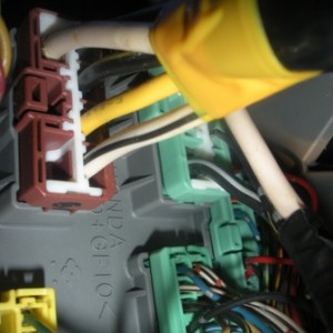
Trunk Release
Door Trigger Location
Viper 5901
➢ Auxiliary harness (H2), 8-pin connector
H2/1 LIGHT GREEN/BLACK (-) 200mA FACTORY ALARM DISARM OUTPUT
H2/2 LIGHT GREEN/WHITE (-) 200mA FACTORY ALARM ARM OUTPUT
H2/3 WHITE/VIOLET (-) 200mA AUX 1 OUTPUT
H2/4 VIOLET/BLACK (-) 200mA AUX 2 OUTPUT
H2/5 WHITE/BLACK (-) 200mA AUX 3 OUTPUT
H2/6 LIGHT BLUE (-) 200mA 2ND UNLOCK OUTPUT
H2/7 GRAY/BLACK (-) DIESEL WAIT TO START INPUT
H2/8 BROWN/BLACK (-) 200Ma HORN HONK OUTPUT
CAR WIRING FOR H2 HARNESS (pictures will be provided for wires that are not obvious.IF left blank, connection is not needed!)
[/COLOR]
PIN--------VEHICLE WIRE---------------LOCATION
H2/1------connect to wire that unlocks the car------ wire is located in the passenger side. look below for the door lock harness. this wire needs to be connected so the factory alarm does not engage when R/S is used or trunk release. (When I did not use this wire the factory alarm would always go off if I R/S or trunk release).
H2/2
H2/3
H2/4
H2/5
H2/6
H2/7
H2/8---------LIGHT GREEN/BLUE (-) ------------@ STEERING COLUMN HARNESS
Viper 5901
➢ Heavy gauge remote start, (H3) 10-pin connector
H3/1 PINK (+) IGNITION 1 INPUT/OUTPUT
H3/2 RED/WHITE (+) FUSED (30A) IGNITION 2 / FLEX RELAY INPUT 87
H3/3 ORANGE (+) ACCESSORY OUTPUT
H3/4 VIOLET (+) STARTER OUTPUT (CAR SIDE OF THE STARTER KILL)
H3/5 GREEN (+) STARTER INPUT (KEY SIDE OF THE STARTER KILL WIRE)
H3/6 RED (+) FUSED (30A) IGNITION 1 INPUT
H3/7 PINK/WHITE (+) IGNITION 2 / FLEX RELAY OUTPUT
H3/8 PINK/BLACK (+) FLEX RELAY INPUT 87A key side (if required) of FLEX RELAY
H3/9 RED/BLACK (+) FUSED (30A) ACCESSORY/STARTER INPUT
H3/10 NC (no connection) NC
CAR WIRING FOR H3 HARNESS (pictures will be provided for wires that are not obvious.IF left blank, connection is not needed!)
PIN--------VEHICLE WIRE---------------LOCATION
H3/1--------BLACK/YELLOW--------------IGNITION SWITCH HARNESS
H3/2--------WHITE--------------IGNITION SWITCH HARNESS
H3/3--------YELLOW--------------IGNITION SWITCH HARNESS
H3/4--------BLACK/WHITE--------------IGNITION SWITCH HARNESS
H3/5--------BLACK/WHITE--------------IGNITION SWITCH HARNESS
H3/6--------WHITE--------------IGNITION SWITCH HARNESS
H3/7--------WHITE/BLACK--------------IGNITION SWITCH HARNESS
H3/8
H3/9--------WHITE--------------IGNITION SWITCH HARNESS
H3/10
IGNITION SWITCH HARNESS
located in the steering column. It is connected from the driver's fuse box to the ignition switch.
Function ------- polarity----------------Vehicle Wire
Constant 12V------------ + -------------------- WHITE
Ignition-------------- + -------------------- BLACK/YELLOW
Accessory----------- + --------------------- YELLOW
Accessory 2--------- + ---------------------- WHITE/BLACK
Starter--------------- + ---------------------- BLACK/WHITE
Ignition Harness Location
****when i first did my research i had trouble understanding how to wire the starter (black/white) wire. What you actually do here is cut the starter wire in half. Half of that wire that is connected to the fusebox is the "car side of the starter kill." The other half that is connected to the ignition switch is called the "key side of the starter kill wire."***
Viper 5901
➢ Remote start input, 5-pin connector
1 BLACK/WHITE (-) NEUTRAL SAFETY SWITCH INPUT
2 VIOLET/WHITE TACHOMETER INPUT WIRE
3 BROWN (+) BRAKE SHUTDOWN INPUT WIRE
4 GRAY N/O or N/C (-) HOOD PIN SWITCH INPUT
5 BLUE/WHITE (-) 200 mA 2ND STATUS/REAR DEFOGGER OUTPUT
CAR WIRING FOR REMOTE START INPUT (pictures will be provided for wires that are not obvious.IF left blank, connection is not needed!)
PIN--------VEHICLE WIRE---------------LOCATION
1--------GROUND (-) -------------------any ground
2--------BLUE----------------------driver side right strut tower in the engine bay or at the distributor or behind the cluster
3--------WHITE/BLACK (+)-----------switch above pedal
4-------- ALARM HOOD PIN (-)--------wherever you mount it
5--------NOT YET----------will be installing this later on, needs a relay!
Brake Shutdown Wire Location
Viper 5901
➢ Remote start auxiliary output, 5-pin
NOT USED
Viper 5901
➢ Door lock harness, 3-pin connector
1 BLUE (+) LOCK (-) UNLOCK OUTPUT
2
3 GREEN (-) LOCK (+) UNLOCK OUTPUT
CAR WIRING FOR Door lock harness, 3-pin connector (pictures will be provided for wires that are not obvious.IF left blank, connection is not needed!)
PIN--------VEHICLE WIRE---------------LOCATION
1----------ORANGE (-)------------------passenger fuse panel
2
3----------BLACK/BLUE (-)--------------passenger fuse panel
Door Lock and Unlock Location
Finish!! Wasn't so bad right? Yep the install wasn't hard just time consuming. Now just program your remote and test if R/S works and everything. I did not buy the bypass module yet so I don't have instructions for it. You won't be able to R/S until you get it but you can test if it works by putting the key in the ign and R/S.
EDITED: Remote Start is finished and installed using ADS-TBSL HA as the bypass module.
Go to idatalink website to download the wiring guide for their bypass module.
ADS-TBSL HA
1/
2/
3/ GREEN/RED- SYNCHRO = this wire connects to the blue wire at the 5 pin green connector located at the key barrel
4/
5/ GRAY/RED- DATA OUT ECM SIDE= this wire is connected to the red data wire that will be cut in half( red data wire that isl going towards the car).. at the 5 pin green connector located at the key barrel
6/ GRAY/YELLOW- DATA IN KEY SIDE= this wire is connected to the red data wire that will be cut in half (red data wire that is going to the key barrel).. at the 5 pin green connector located at the key barrel
7/
8/
9/ PINK- IGNITION INPUT = this wire is connected to the yellow/black wire at the 5 pin green connector located at the key barrel
Last edited: