

puzzlemaster94
6GA Connoisseur
I am attempting to answer most of the questions that surround Richie's Harness and what it does. I purchased a V4 version secondhand from a Facebook friend.
Wiring Pinout Diagrams can be found here: http://6thgenaccord.com/forums/showthread.php?t=43420&page=41
Few things that need to be said:
This will only work for the 6th Gen Accord chassis
You need AUTOMATIC sensors and a AUTOMATIC J32a2 for this to work
---These are the easiest to find of the J32a2's, so not really an issue
---01-03 Auto CL/TL Type S Cars will have these things
You will utilize the J32a2 automatic engine harness and ECU
---CL/TL Type S ECU's and automatic engine harnesses are identical
---Both ECU's have the same part number
You will need to have your ECU's immobilizer removed or get a key/ignition cylinder/ECU from the same car
You will NOT use any of the automatic transmission plugs, as none of them will work with the manual transmission
Richie (RV6 Performace) no longer makes this harness, so finding one will be a challenge
I highly recommend soldering and heat-shrinking every connection
Now to the rest of the DIY:
I am going to be starting from the point of the J32 6MT swap already being completed. Now I am using a 7th Gen Accord V6 6speed, and everything has lined up so far.
The 7th Gen Accord Manual Transmission has 4 sensors on the entire thing. They are:
Reverse Lockout Solenoid
Reverse Switch
Mainshaft Speed Sensor
Countershaft Speed Sensor
You will have to connect to all of these for the module to function properly.
When I bought my module, the wiring and plugs for these sensors was included, but some of the wires were not as long as they needed to be, or just cut and no label on them. Now you do not have to make this into a harness, but I decided it would be easy to keep everything in order.
So I'll start with the harness building: You will need:
-Soldering Iron/Gun
-Solder
-Heatshrink
-Wire (I used 20 gauge, factory gauge is 22)
-Electrical Tape
-Multimeter
-Time. Lots of time
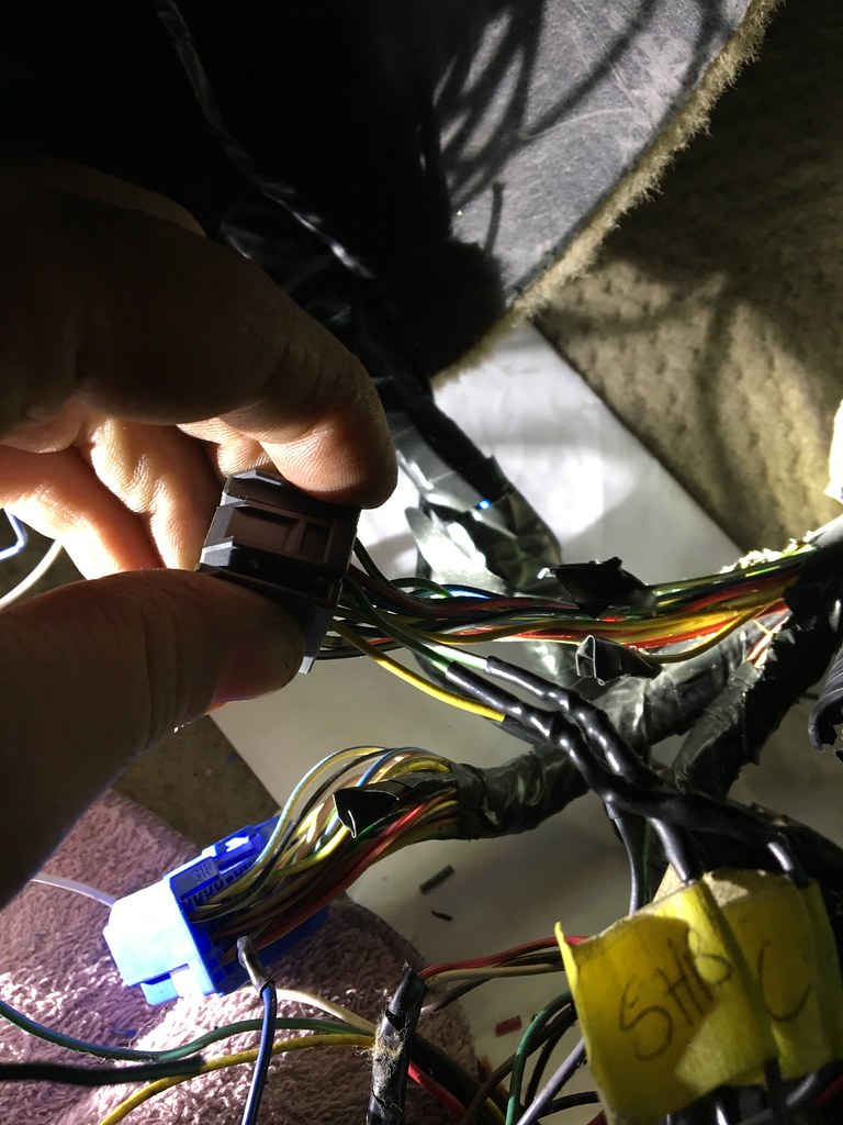
First off, I recieved my harness as this.
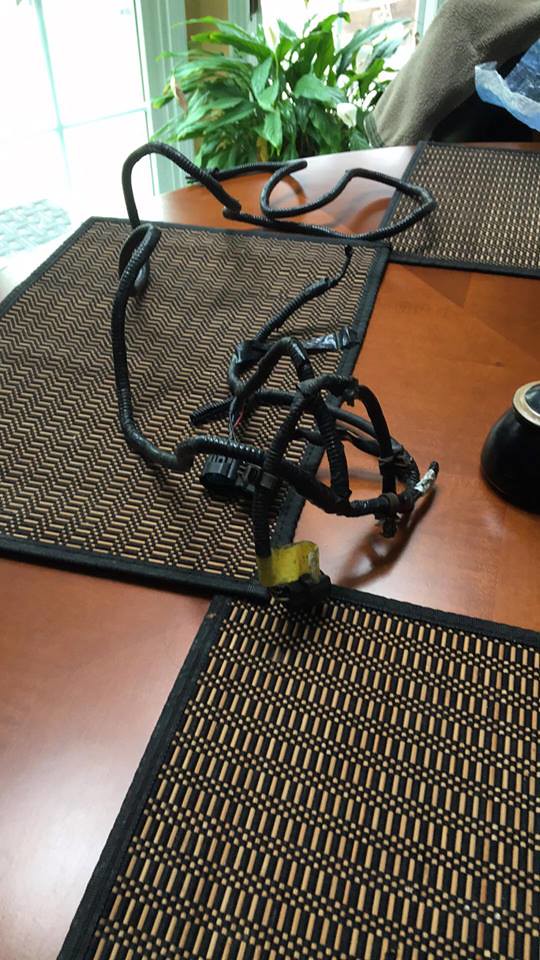 Harness Extension by Evan Aschbacher, on Flickr
Not in the worst of shape, but not complete either. It did not have a reverse switch plug, and quite a few of the wires were not labeled and changed colors.
So since I had a 03 CLS6 Engine harness laying around, I cut the plug off of that.
--I plan on trying to 3D print a version of this plug that will work, to make these more accessible.
 Richie's Harness by Evan Aschbacher, on Flickr
This is the plug in the spot where it needs to go. Two wire plug, one ground and one power. Polarity also does not matter on this plug, but I chose the black wire as the ground.
 Richie's Harness by Evan Aschbacher, on Flickr
As you can see, it is soldered and heat-shrinked to my blue wire, for extending the wiring. I then soldered this into the harness I was provided. The rest of the harness had the 2 speed sensors and reverse lockout solenoid already wired with plugs, so that was a plus.
 Reverse Lockout Solenoid by Evan Aschbacher, on Flickr
--Reverse Lockout solenoid. If you do not have this harness, then a black transmission 2 wire plug can be cut off and wired into for this.
 Richie's Harness Wiring by Evan Aschbacher, on Flickr
--These can be used for the reverse Lockout solenoid
Now the Making of the Harness:
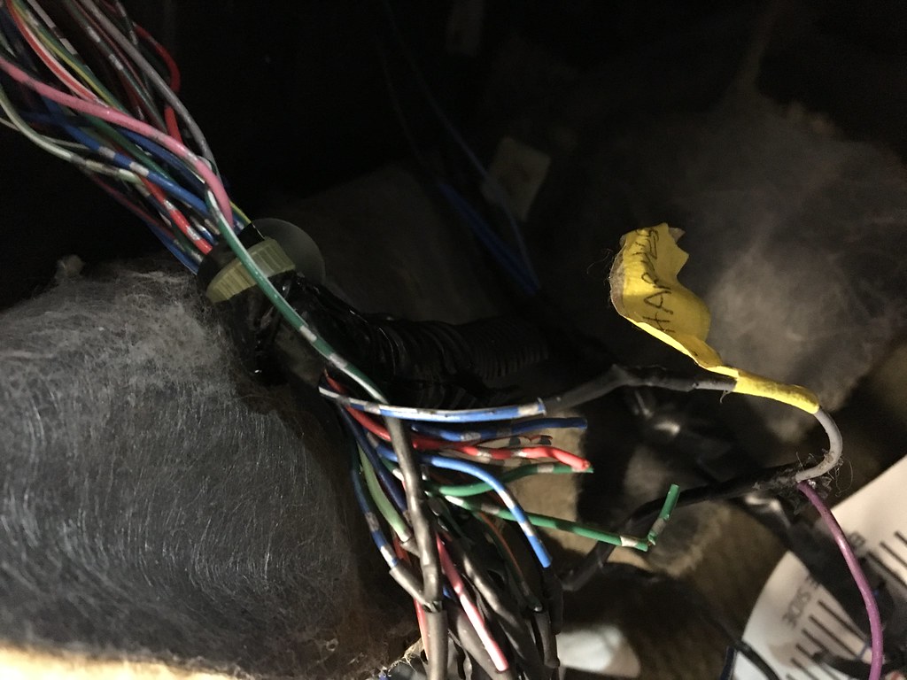
After getting everything to the length I desired, I took it out of the car and started to get everything situated. The harness that I was provided was long enough for me to run it into the cabin and to everything I needed it to reach.
 Richie's Harness by Evan Aschbacher, on Flickr
So now I have two blue wires running off the reverse switch plug, separate from the rest of the harness. I recommend running it separately, as these wires need to reach the drivers side fuse box, whereas the rest of the wires need to reach the ECU location (long enough to get to passenger floor).
Next, I taped the blue wires together.
 Richie's Harness by Evan Aschbacher, on Flickr
Next, I ran wire tube (the hard plastic shell with one cut all the way up the tube) around the blue wires and taped over that also.
 Richie's Harness by Evan Aschbacher, on Flickr
The completed version for me. I used a lot of electrical tape.
--You may not need as much tape as I used, I took some off to route the two ends of the harness around in the cabin.
The wire colors at the end follow as:
Red, Blue, Black and Orange in One bunch, and Green and Black in another bunch.
Red:- Power for both Speed Sensors
Blue - Signal for Speed Sensor A
Black - Ground of both Speed Sensors
Orange -Signal for Speed Sensor B
Green - Reverse Lockout Power
Black - Reverse Lockout Ground
And the blue wires that were added in a separate loom. One is power and one is ground. Polarity doesn't matter for the reverse switch.
Now I had an option, I could tap into the factory engine harness and run it with that, or find an unused hole in the firewall and route the wires to the cabin that way. I chose the second option. I found a unused hole, right under where the brake booster vacuum line and fuel lines run. To the left of the brake booster.
 Richie's Harness by Evan Aschbacher, on Flickr
--You can see the taped harness entering the cabin, on the right side of the picture.
Once you get the harness into the cabin, route the two wires for the reverse switch to the drivers side fusebox and the other set to the passenger side floor, to connect with the module and engine harness plugs.
 Richie's Harness Harness Extension by Evan Aschbacher, on Flickr
And now it meets the mess of everything.
 Richie's Harness by Evan Aschbacher, on Flickr
--In this photo, nothing is wired up, just everything in position to be wired.
Now here are the directions for Richie's Harness:
 Directions for Richie's Swap by Evan Aschbacher, on Flickr
 Directions for Richie's Swap Speed Sensors by Evan Aschbacher, on Flickr
--Here, you can see the speed sensor plugs. Three wire plugs
 Directions for Richie's Swap Wire Extensions by Evan Aschbacher, on Flickr
--Richie ran the reverse switch wires not in the harness, whereas I ran mine with the harness. Only difference here
 Directions for Richie's Swap Reverse Switch by Evan Aschbacher, on Flickr
--Where the reverse switch wire connects, other is grounded
 Richie's Swap Diagram by Evan Aschbacher, on Flickr
--This is how everything is wired up, regarding the main stuff. Shows how the module works and what it is connected to. Looks intimidating, but go over it a few times and makes sense.
Here is Richie's module in person. Everything is labeled and has a different colored wire going to most connections, which makes it very easy to decipher.
 Unboxing of the Module 2 by Evan Aschbacher, on Flickr
Now a few of the other wires from the module have to cross over to the drivers side and vice versa. The purple wire has to be extended to reach the ignition wires on the drivers side, and the pedal switch (clutch pedal) wires have to reach the module on the passenger side.
Now the actual wiring of the Module:
Now we are going to be looking at the wiring diagram posted above quite frequently from here on out. Just so you know what wire I am talking about and such.
Once the harness is in the car, now comes the hard part. The two from the reverse switch must connect to the driver's side fusebox, so I'll start there.
Here is the one of the wires (white and top of E-Connector) that is cut. One blue wire needs to go to this, and the other one gets grounded to the nearby ground.
 https://flic.kr/p/RVx5p2
You'll notice the white wire in slot #10 is cut (the top white wire). One of the blue wires from the reverse switch needs to connect into this, while the other gets grounded to the dash on a nearby bolt.
I also had #8 wire (blue/white) cut and have since re-soldered and connected to it's stock location. It was cut for the NSS on the true 6MT wiring, but it does not need to be cut for Richie's. So just pretend it is normal.
Final product. Ground is not pictured, but you will see it is very close.
 https://flic.kr/p/TatZUB
Now the ignition switch/cylinder. Only wire needs to be soldered on here. Connect it to the black/white wire on the switch. Now I highly recommend that you just shave the coating away from where you solder the wire, so it will be much easier. I cut it and it took some time and fast soldering to get the wires to get back together.
 Richie's Harness by Evan Aschbacher, on Flickr
And where I cut
 Richie's Harness by Evan Aschbacher, on Flickr
Finished product
 Richie's Harness by Evan Aschbacher, on Flickr
Now the third part, the clutch switch.
The clutch switch (I used a 5MT Accord clutch connector) is a yellow 2 pin connector. The blue wire is power and the black wire is ground. I just extended both of these to the passenger side of the car to reach the module. Simple stuff.
Now Comes the Engine Harness Connections:
-- I will list every connection in a list here to make it less confusing. But I am explaining just what the diagram above is showing (wiring diagram)
Accord Dash Harness
A9-(Blue/White) VSSOUT. The gray lead from Richies harness will go into the harness and the blue lead from Richies will go into the plug.
Now an example of how I am going to be listing the wires:
Wire Name and Color------What the wire does-------What wire from Richies gets wired in
Engine Harness
B1-(Yellow/Black)--IGP1 (Power Source)------------------------Red lead from Richies gets wired in here
B2-(Black)----------PG1 (Power Ground)-------------------------Black wire from Richies gets wired in here
B8-(White)---------LSA (A/T Clutch Pressure Control A-)-------White wire from the load module gets wired in here
B13 (Green/Red)---LSC (A/T Clutch Pressure Control C+)------Green wire from the load module gets wired in here
B14 (Blue/White)--ATPNP (A/T Gear Position Switch)-----------Brown wire from Richies gets wired in here
B17 (Red)---------LSA+ (A/T Clutch Pressure Control A+)-----Red wire from the load module gets wired in here
B18 (Green)-------LSB- (A/T Clutch Pressure Control B-)------Green wire from the load module gets wired in here
B24 (Red/Blue)---LSC- (A/T Clutch Pressure Control C-)-------Red wire from the load module gets wired in here
B25 (Brown/White)-LSB+ (A/T Clutch Pressure Control B+)--Brown wire from the load module gets wired in here
C24 (Blue/Yellow)--TATF (ATF Temperature Sensor)-----------Blue wire from the load module gets wired in here
D1 (Yellow)--------LC (Lock-up Control Valve)-----------------One of the gray wires from the load module gets wired in here (Doesn't matter which gray wire)
D2 (Green/White)-SHB (Shift Control Valve B)----------------One of the gray wires from the load module gets wired in here (Doesn't matter which gray wire)
D3 (Green)--------SHC (Shift Control Valve C)----------------One of the gray wires from the load module gets wired in here (Doesn't matter which gray wire)
D6 (White)--------ATPR (A/T Gear Position Switch)-----------This wire just gets cut. No wires attach to this
D7 (Blue/Yellow)-SHA (Shift Control Valve A)-----------------One of the gray wires from the load module gets wired in here (Doesnt matter which gray wire)
D10 (Blue)--------NC (Countershaft Speed Sensor)-----------The blue lead from Richies wires into the harness end and the yellow lead wires into the plug end
D11 (Red)---------NM (Mainshaft Speed Sensor)--------------The red lead from Richies wires into the harness end and the green lead wires into the plug end
D15(Blue)---------ATP2 (A/T Gear Position Switch)-----------The white lead from Richies wires in here
I will start with the first wire on the diagram. This is A9 and the only wire you need to tap into for the A plug. It is a blue and white wire used for Vehicle Speed Sensor Output.
The gray wire from the module needs to go into the harness towards the plug and the purple goes into the connector. This is so the signal has to run through the module before it gets to the ECU. So cutting this wire is the only option to do this.
 https://flic.kr/p/Tau3Hn
---Ignore the other cut wires in this picture. I had to re-solder my factory Accord connector back on and a lot of the wires are the exact same color. So I had to figure out which ones did what before I connected them.
And the purple
 https://flic.kr/p/T6UAgj
Now onto Connector B. This is the biggest gray plug on the engine harness.
Here you have a few wires to tap into.
The first wire is B1 (yellow/black). The very first wire on the connector. You do not need to cut into this one, just tap into it and solder the red wire into it.
 Richie's
Next is B2 (black wire), which is the same process as before. This wire is right next to B1 (the one you just tapped into)
 https://flic.kr/p/SVCTr9
Next is B8(white), and this is on the load module. This is the littler metal box with no connectors on it. Just wires coming out of a opening. We are going to use the white wire to connect to the white wire coming out of the engine harness. Now you just cut the wire and tape the end that will not be connected to anything and wire in the load module wire to the connector.
 https://flic.kr/p/SzCyiN
--White wire in the left hand area of the photo
Next is B13(Green/Red) and we are doing the same process as the last wire. Cut the wire and wire it to the connector and tape the other end that will stay unconnected in the engine harness loom.
https://flic.kr/p/SzCyiN
--Same picture as above, but you can clearly see the wire being tapped into
Now here is the part where I forgot to take a bunch of pictures of the wiring I did, I got really focused lol. But it is the exact same process as before
Next is B14, and we are back to the Richie's Swap Magic Box. This time, the brown wire ATPNP wire will wire into B14. But no cutting of wires, just strip the wire and wire it in.
--No pictures of this
Next is B17, back onto the load module. This is one of the red wires, the wire right next to the white one wired in a few steps back.
Next is B18, the green wire next to the other red wire on the load module. This is the last green wire on the load module.
Next is B24, the red wire next to the green wire we just wired into B18. This is the last red wire on the load module
Next is B25, the only brown wire on the load module. This is also the last connection made on the B connector of the engine harness.
Next is the C Plug. We only have one connection here, C24. This is the only blue plug on the engine harness
C24 is the ATF temp sensor wire (Blue/Yellow) and this wire to the only blue wire on the load module.
 https://flic.kr/p/RVx2MZ
Now we are on the last plug. The D plug, 15pin and the smallest plug on the engine harness.
We start at D1. Now the module said that wiring on the grey wires does not matter, so I just wired the four gray wires to each wire in the engine harness in no particular order.
D1-gray
D2-gray
D3-gray
D7-gray.
Notice how D6 is not included in this. D6 is just cut and not wired to anything.
https://flic.kr/p/RVx2MZ
Now every wire on the load module should be wired in. Its now back to the load module for the last three wires.
Here is where Richie's and my wiring differ:
Richie has a blue and a red speed sensor wire going to the engine harness for D10 (blue) and D11 (red).
I had previously wired these to the matching wires from the harness coming from the engine bay. I have not connected these since, and the car functions just fine. I have heard of this way from others and it seems to be an ok thing to do.
 https://flic.kr/p/RT1gCj
-This is to show the blue and wire coming from the engine bay and the Richie's box. I have these wired together and no issue.
So for D10, I just connected the yellow wire from the module to the plug and cut the other end and left it taped up.
For D11, I did the same thing, just with the green wire from the module.
Now the very last wire, D15. The very last wire going to the D plug. Just cut the wire and wire in the last white wire from the harness and then you are done.
Words of Encouragement:
Even if you do not have a harness made for this, you will only need three plugs and some wire. All of these plus (speed sensor A & B and the reverse switch plug) can be sourced from the donor trans car or found at a junkyard. The black reverse lockout plug can be cut from the auto engine harness, as you will not use any of the automatic transmission plugs on the engine harness.
Please feel free to leave a comment if you see anything that I missed. Rep if you found helpful
I'd like to thank Chris (RedRyder), Jay (J35cg2), Jack (old7cg2), Varnell, FNCONE, TurboAccord99, AND many more that have helped me throughout this
Wiring Pinout Diagrams can be found here: http://6thgenaccord.com/forums/showthread.php?t=43420&page=41
Few things that need to be said:
This will only work for the 6th Gen Accord chassis
You need AUTOMATIC sensors and a AUTOMATIC J32a2 for this to work
---These are the easiest to find of the J32a2's, so not really an issue
---01-03 Auto CL/TL Type S Cars will have these things
You will utilize the J32a2 automatic engine harness and ECU
---CL/TL Type S ECU's and automatic engine harnesses are identical
---Both ECU's have the same part number
You will need to have your ECU's immobilizer removed or get a key/ignition cylinder/ECU from the same car
You will NOT use any of the automatic transmission plugs, as none of them will work with the manual transmission
Richie (RV6 Performace) no longer makes this harness, so finding one will be a challenge
I highly recommend soldering and heat-shrinking every connection
Now to the rest of the DIY:
I am going to be starting from the point of the J32 6MT swap already being completed. Now I am using a 7th Gen Accord V6 6speed, and everything has lined up so far.
The 7th Gen Accord Manual Transmission has 4 sensors on the entire thing. They are:
Reverse Lockout Solenoid
Reverse Switch
Mainshaft Speed Sensor
Countershaft Speed Sensor
You will have to connect to all of these for the module to function properly.
When I bought my module, the wiring and plugs for these sensors was included, but some of the wires were not as long as they needed to be, or just cut and no label on them. Now you do not have to make this into a harness, but I decided it would be easy to keep everything in order.
So I'll start with the harness building: You will need:
-Soldering Iron/Gun
-Solder
-Heatshrink
-Wire (I used 20 gauge, factory gauge is 22)
-Electrical Tape
-Multimeter
-Time. Lots of time
First off, I recieved my harness as this.
Harness Extension by Evan Aschbacher, on FlickrNot in the worst of shape, but not complete either. It did not have a reverse switch plug, and quite a few of the wires were not labeled and changed colors.
So since I had a 03 CLS6 Engine harness laying around, I cut the plug off of that.
--I plan on trying to 3D print a version of this plug that will work, to make these more accessible.
Richie's Harness by Evan Aschbacher, on FlickrThis is the plug in the spot where it needs to go. Two wire plug, one ground and one power. Polarity also does not matter on this plug, but I chose the black wire as the ground.
Richie's Harness by Evan Aschbacher, on FlickrAs you can see, it is soldered and heat-shrinked to my blue wire, for extending the wiring. I then soldered this into the harness I was provided. The rest of the harness had the 2 speed sensors and reverse lockout solenoid already wired with plugs, so that was a plus.
Reverse Lockout Solenoid by Evan Aschbacher, on Flickr--Reverse Lockout solenoid. If you do not have this harness, then a black transmission 2 wire plug can be cut off and wired into for this.
Richie's Harness Wiring by Evan Aschbacher, on Flickr--These can be used for the reverse Lockout solenoid
Now the Making of the Harness:
After getting everything to the length I desired, I took it out of the car and started to get everything situated. The harness that I was provided was long enough for me to run it into the cabin and to everything I needed it to reach.
Richie's Harness by Evan Aschbacher, on FlickrSo now I have two blue wires running off the reverse switch plug, separate from the rest of the harness. I recommend running it separately, as these wires need to reach the drivers side fuse box, whereas the rest of the wires need to reach the ECU location (long enough to get to passenger floor).
Next, I taped the blue wires together.
Richie's Harness by Evan Aschbacher, on FlickrNext, I ran wire tube (the hard plastic shell with one cut all the way up the tube) around the blue wires and taped over that also.
Richie's Harness by Evan Aschbacher, on FlickrThe completed version for me. I used a lot of electrical tape.
--You may not need as much tape as I used, I took some off to route the two ends of the harness around in the cabin.
The wire colors at the end follow as:
Red, Blue, Black and Orange in One bunch, and Green and Black in another bunch.
Red:- Power for both Speed Sensors
Blue - Signal for Speed Sensor A
Black - Ground of both Speed Sensors
Orange -Signal for Speed Sensor B
Green - Reverse Lockout Power
Black - Reverse Lockout Ground
And the blue wires that were added in a separate loom. One is power and one is ground. Polarity doesn't matter for the reverse switch.
Now I had an option, I could tap into the factory engine harness and run it with that, or find an unused hole in the firewall and route the wires to the cabin that way. I chose the second option. I found a unused hole, right under where the brake booster vacuum line and fuel lines run. To the left of the brake booster.
Richie's Harness by Evan Aschbacher, on Flickr--You can see the taped harness entering the cabin, on the right side of the picture.
Once you get the harness into the cabin, route the two wires for the reverse switch to the drivers side fusebox and the other set to the passenger side floor, to connect with the module and engine harness plugs.
Richie's Harness Harness Extension by Evan Aschbacher, on FlickrAnd now it meets the mess of everything.
Richie's Harness by Evan Aschbacher, on Flickr--In this photo, nothing is wired up, just everything in position to be wired.
Now here are the directions for Richie's Harness:
Directions for Richie's Swap by Evan Aschbacher, on FlickrDirections for Richie's Swap Speed Sensors by Evan Aschbacher, on Flickr--Here, you can see the speed sensor plugs. Three wire plugs
Directions for Richie's Swap Wire Extensions by Evan Aschbacher, on Flickr--Richie ran the reverse switch wires not in the harness, whereas I ran mine with the harness. Only difference here
Directions for Richie's Swap Reverse Switch by Evan Aschbacher, on Flickr--Where the reverse switch wire connects, other is grounded
Richie's Swap Diagram by Evan Aschbacher, on Flickr--This is how everything is wired up, regarding the main stuff. Shows how the module works and what it is connected to. Looks intimidating, but go over it a few times and makes sense.
Here is Richie's module in person. Everything is labeled and has a different colored wire going to most connections, which makes it very easy to decipher.
Unboxing of the Module 2 by Evan Aschbacher, on FlickrNow a few of the other wires from the module have to cross over to the drivers side and vice versa. The purple wire has to be extended to reach the ignition wires on the drivers side, and the pedal switch (clutch pedal) wires have to reach the module on the passenger side.
Now the actual wiring of the Module:
Now we are going to be looking at the wiring diagram posted above quite frequently from here on out. Just so you know what wire I am talking about and such.
Once the harness is in the car, now comes the hard part. The two from the reverse switch must connect to the driver's side fusebox, so I'll start there.
Here is the one of the wires (white and top of E-Connector) that is cut. One blue wire needs to go to this, and the other one gets grounded to the nearby ground.
https://flic.kr/p/RVx5p2 You'll notice the white wire in slot #10 is cut (the top white wire). One of the blue wires from the reverse switch needs to connect into this, while the other gets grounded to the dash on a nearby bolt.
I also had #8 wire (blue/white) cut and have since re-soldered and connected to it's stock location. It was cut for the NSS on the true 6MT wiring, but it does not need to be cut for Richie's. So just pretend it is normal.
Final product. Ground is not pictured, but you will see it is very close.
https://flic.kr/p/TatZUBNow the ignition switch/cylinder. Only wire needs to be soldered on here. Connect it to the black/white wire on the switch. Now I highly recommend that you just shave the coating away from where you solder the wire, so it will be much easier. I cut it and it took some time and fast soldering to get the wires to get back together.
Richie's Harness by Evan Aschbacher, on FlickrAnd where I cut
Richie's Harness by Evan Aschbacher, on FlickrFinished product
Richie's Harness by Evan Aschbacher, on FlickrNow the third part, the clutch switch.
The clutch switch (I used a 5MT Accord clutch connector) is a yellow 2 pin connector. The blue wire is power and the black wire is ground. I just extended both of these to the passenger side of the car to reach the module. Simple stuff.
Now Comes the Engine Harness Connections:
-- I will list every connection in a list here to make it less confusing. But I am explaining just what the diagram above is showing (wiring diagram)
Accord Dash Harness
A9-(Blue/White) VSSOUT. The gray lead from Richies harness will go into the harness and the blue lead from Richies will go into the plug.
Now an example of how I am going to be listing the wires:
Wire Name and Color------What the wire does-------What wire from Richies gets wired in
Engine Harness
B1-(Yellow/Black)--IGP1 (Power Source)------------------------Red lead from Richies gets wired in here
B2-(Black)----------PG1 (Power Ground)-------------------------Black wire from Richies gets wired in here
B8-(White)---------LSA (A/T Clutch Pressure Control A-)-------White wire from the load module gets wired in here
B13 (Green/Red)---LSC (A/T Clutch Pressure Control C+)------Green wire from the load module gets wired in here
B14 (Blue/White)--ATPNP (A/T Gear Position Switch)-----------Brown wire from Richies gets wired in here
B17 (Red)---------LSA+ (A/T Clutch Pressure Control A+)-----Red wire from the load module gets wired in here
B18 (Green)-------LSB- (A/T Clutch Pressure Control B-)------Green wire from the load module gets wired in here
B24 (Red/Blue)---LSC- (A/T Clutch Pressure Control C-)-------Red wire from the load module gets wired in here
B25 (Brown/White)-LSB+ (A/T Clutch Pressure Control B+)--Brown wire from the load module gets wired in here
C24 (Blue/Yellow)--TATF (ATF Temperature Sensor)-----------Blue wire from the load module gets wired in here
D1 (Yellow)--------LC (Lock-up Control Valve)-----------------One of the gray wires from the load module gets wired in here (Doesn't matter which gray wire)
D2 (Green/White)-SHB (Shift Control Valve B)----------------One of the gray wires from the load module gets wired in here (Doesn't matter which gray wire)
D3 (Green)--------SHC (Shift Control Valve C)----------------One of the gray wires from the load module gets wired in here (Doesn't matter which gray wire)
D6 (White)--------ATPR (A/T Gear Position Switch)-----------This wire just gets cut. No wires attach to this
D7 (Blue/Yellow)-SHA (Shift Control Valve A)-----------------One of the gray wires from the load module gets wired in here (Doesnt matter which gray wire)
D10 (Blue)--------NC (Countershaft Speed Sensor)-----------The blue lead from Richies wires into the harness end and the yellow lead wires into the plug end
D11 (Red)---------NM (Mainshaft Speed Sensor)--------------The red lead from Richies wires into the harness end and the green lead wires into the plug end
D15(Blue)---------ATP2 (A/T Gear Position Switch)-----------The white lead from Richies wires in here
I will start with the first wire on the diagram. This is A9 and the only wire you need to tap into for the A plug. It is a blue and white wire used for Vehicle Speed Sensor Output.
The gray wire from the module needs to go into the harness towards the plug and the purple goes into the connector. This is so the signal has to run through the module before it gets to the ECU. So cutting this wire is the only option to do this.
https://flic.kr/p/Tau3Hn ---Ignore the other cut wires in this picture. I had to re-solder my factory Accord connector back on and a lot of the wires are the exact same color. So I had to figure out which ones did what before I connected them.
And the purple
https://flic.kr/p/T6UAgjNow onto Connector B. This is the biggest gray plug on the engine harness.
Here you have a few wires to tap into.
The first wire is B1 (yellow/black). The very first wire on the connector. You do not need to cut into this one, just tap into it and solder the red wire into it.
Richie'sNext is B2 (black wire), which is the same process as before. This wire is right next to B1 (the one you just tapped into)
https://flic.kr/p/SVCTr9Next is B8(white), and this is on the load module. This is the littler metal box with no connectors on it. Just wires coming out of a opening. We are going to use the white wire to connect to the white wire coming out of the engine harness. Now you just cut the wire and tape the end that will not be connected to anything and wire in the load module wire to the connector.
https://flic.kr/p/SzCyiN--White wire in the left hand area of the photo
Next is B13(Green/Red) and we are doing the same process as the last wire. Cut the wire and wire it to the connector and tape the other end that will stay unconnected in the engine harness loom.
https://flic.kr/p/SzCyiN--Same picture as above, but you can clearly see the wire being tapped into
Now here is the part where I forgot to take a bunch of pictures of the wiring I did, I got really focused lol. But it is the exact same process as before
Next is B14, and we are back to the Richie's Swap Magic Box. This time, the brown wire ATPNP wire will wire into B14. But no cutting of wires, just strip the wire and wire it in.
--No pictures of this
Next is B17, back onto the load module. This is one of the red wires, the wire right next to the white one wired in a few steps back.
Next is B18, the green wire next to the other red wire on the load module. This is the last green wire on the load module.
Next is B24, the red wire next to the green wire we just wired into B18. This is the last red wire on the load module
Next is B25, the only brown wire on the load module. This is also the last connection made on the B connector of the engine harness.
Next is the C Plug. We only have one connection here, C24. This is the only blue plug on the engine harness
C24 is the ATF temp sensor wire (Blue/Yellow) and this wire to the only blue wire on the load module.
https://flic.kr/p/RVx2MZNow we are on the last plug. The D plug, 15pin and the smallest plug on the engine harness.
We start at D1. Now the module said that wiring on the grey wires does not matter, so I just wired the four gray wires to each wire in the engine harness in no particular order.
D1-gray
D2-gray
D3-gray
D7-gray.
Notice how D6 is not included in this. D6 is just cut and not wired to anything.
https://flic.kr/p/RVx2MZNow every wire on the load module should be wired in. Its now back to the load module for the last three wires.
Here is where Richie's and my wiring differ:
Richie has a blue and a red speed sensor wire going to the engine harness for D10 (blue) and D11 (red).
I had previously wired these to the matching wires from the harness coming from the engine bay. I have not connected these since, and the car functions just fine. I have heard of this way from others and it seems to be an ok thing to do.
https://flic.kr/p/RT1gCj-This is to show the blue and wire coming from the engine bay and the Richie's box. I have these wired together and no issue.
So for D10, I just connected the yellow wire from the module to the plug and cut the other end and left it taped up.
For D11, I did the same thing, just with the green wire from the module.
Now the very last wire, D15. The very last wire going to the D plug. Just cut the wire and wire in the last white wire from the harness and then you are done.
Words of Encouragement:
Even if you do not have a harness made for this, you will only need three plugs and some wire. All of these plus (speed sensor A & B and the reverse switch plug) can be sourced from the donor trans car or found at a junkyard. The black reverse lockout plug can be cut from the auto engine harness, as you will not use any of the automatic transmission plugs on the engine harness.
Please feel free to leave a comment if you see anything that I missed. Rep if you found helpful
I'd like to thank Chris (RedRyder), Jay (J35cg2), Jack (old7cg2), Varnell, FNCONE, TurboAccord99, AND many more that have helped me throughout this
Last edited:
 .......Me After I re-read your last sentance
 ......I think this was you lol